


8
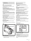
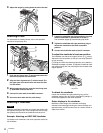
Overview
The RET 1 button has priority over the RET (2/3/4) button if
both buttons are pressed.
c DISPLAY/MENU switch
This switch functions the same as the DISPLAY/MENU switch
on the front (page 6).
d ASSIGNABLE button
You can assign a function with ASSIGNABLE REAR on the
<SWITCH ASSIGN1> page of the OPERATION menu.
e Menu control knob (rotary encoder)
This knob functions the same as the menu control knob on the
front (page 6).
f LEVEL/MIC (intercom level control/microphone)
switch
To determine whether to use the INTERCOM LEVEL control
(page 7) on the front and to turn the intercom headset
microphone ON/OFF.
g Line select switch
To select the intercom line:
PROD: Producer line
ENG: Engineer line
h INCOM (intercom) level control
To adjust the intercom audio listening level.
i PGM1 (program 1) and PGM2 (program 2) controls
To adjust the audio listening level of program 1 or program 2,
respectively.
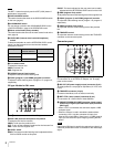
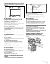
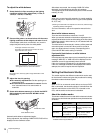
CE type: Models for PAL areas
1 to 5 are the same as those of the UC type.
f MIC LINE (intercom microphone line) switch
To select the talk line for intercom:
PROD: To talk over the producer line
OFF: To turn off the headset microphone for the intercom line
ENG: To talk over the engineer line
g LEVEL switch
REAR: The intercom audio listening level is adjusted with the
ENG or PROD control on this panel.
FRONT: The levels adjusted on the rear panel can be totally
adjusted with the INTERCOM LEVEL control on the front.
h ENG (engineer line) control
To adjust the intercom audio listening level of the engineer line.
i PGM1 (program 1) and PGM2 (program 2) controls
To adjust the audio listening level of program 1 or program 2,
respectively.
j PROD (producer line) control
To adjust the intercom audio listening level of the producer
line.
k TRACKER control
To adjust the intercom audio listening level at the TRACKER
connector on the connector panel.
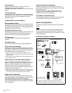
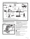
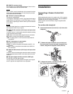
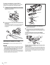
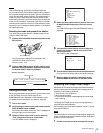
Connector panel
a DC IN (DC power supply input) connector (XLR 4-pin)
For connection to an AC-DN10 AC Adaptor, etc. to supply
power to the camera.
b DC OUT (DC power supply output) connector (4-pin)
To supply power to a script light or equivalent (12 V DC, max.
0.5 A).
c TRACKER connector (10-pin)
For external interfaces, such as intercom and tally.
d RET CTRL (return control) connector (6-pin)
For connection to a CAC-6 Return Video Selector.
e PROMPTER/GENLOCK/RET (prompter signal output/
external sync signal input/VBS return input) connector
(BNC type)
• When a CCU is connected, this connector outputs a VBS
prompter signal.
• When the camera is used in standalone status without
connecting a CCU, use this connector for input of an
external sync signal (BB or 3-level sync). If a VBS signal is
input, you can check the input image by pressing the RET
button.
Even when a BB signal is used for the external sync signal, no
subcarrier phase-lock function is available for the VBS output
signal.
Note
Switch position INTERCOM LEVEL
control on the front
Headset microphone
REAR/ON Inactive ON
REAR/OFF OFF
FRONT/OFF Active
PGM1
ENG PROD TRACKER
PGM2
ASSIGNABLE
234
RET1 RET
PROD
ENG
OFF
LINE
LEVEL
REAR
FRONT
MIC
INTERCOM EARPHONE
DISPLAY
MENU
OFF
12 345
678 0 q
a
9
Note
DC OUT
AUDIO IN
CH1 CH2
TEST
OUT
SDI
DC IN
10.5-17V
+
48V
MICLINE
+
48V
MICLINE
REAR
MIC1
FRONT
REMOTE
RET CTRL
PROMPTER
/GENLOCK
/RET
TRACKER
1234567
890qa