


5
Overview
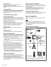
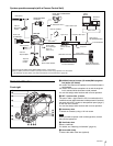
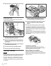
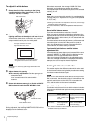
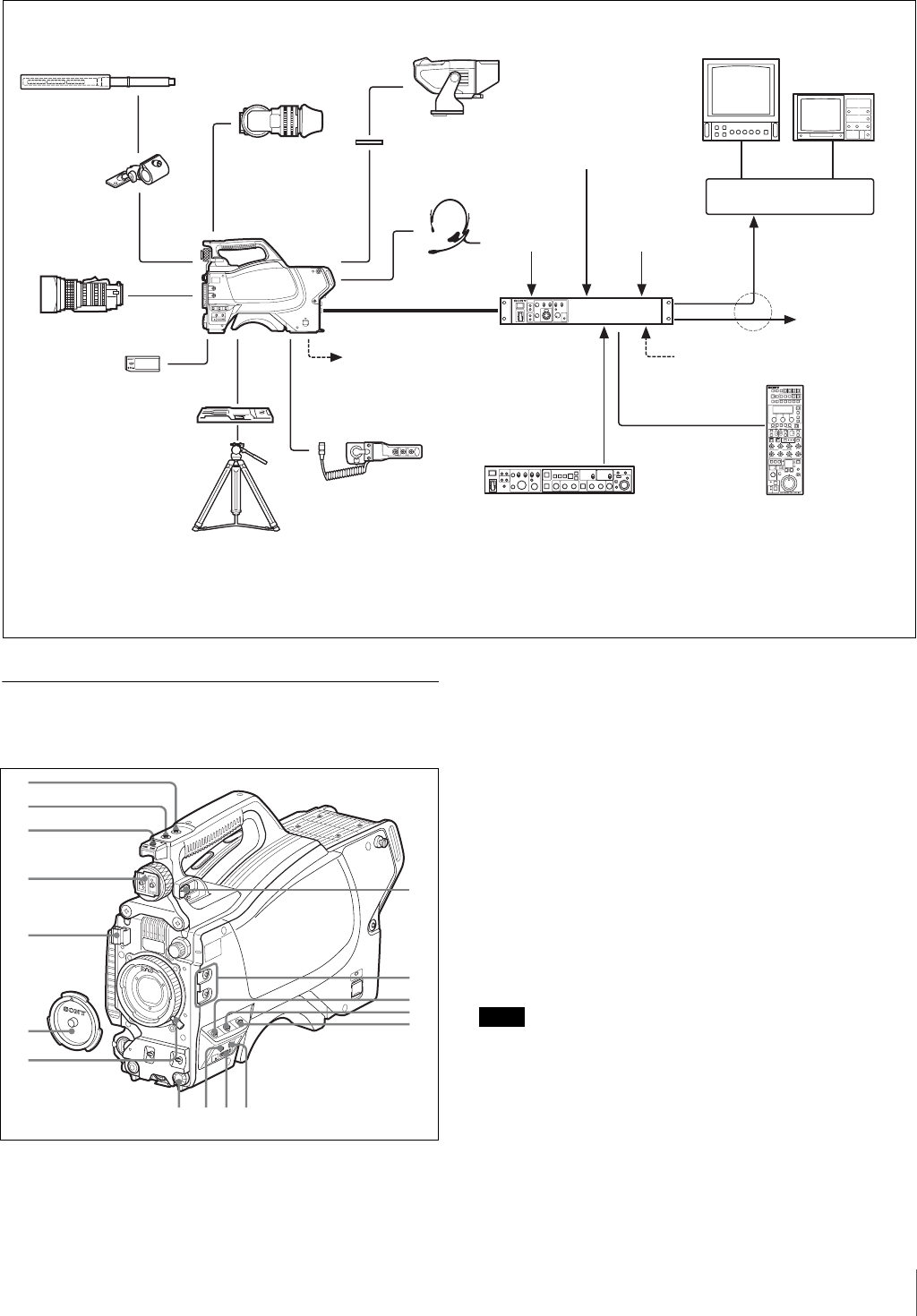
System operation example (with a Camera Control Unit)
Parts Identification
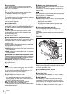
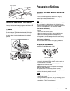
Front right
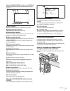
a INCOM (intercom) button (UC model)/ENG (engineer
line) button (CE model)
UC model: The intercom microphone is on while this button is
held pressed.
CE model: The intercom microphone is on and the engineer
line is selected while this button is held pressed.
You can also assign other functions with a menu operation.
b RET 1 (return video 1) button
The return video 1 signal from the CCU is monitored on the
viewfinder screen while this button is held pressed. It functions
the same as the RET 1 button on the operation panel (page 7)
on the rear of the camera.
You can also assign other functions with a menu operation.
c Accessory shoe
To attach an accessory using a 1/4-inch screw.
When you wish to replace it with a slide-type shoe, consult
Sony service personnel.
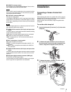
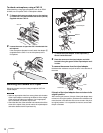
d Viewfinder shoe
Mount a viewfinder.
For details, see “Attaching a Viewfinder” (page 10).
e Lens cable clamp
To secure the cable of the lens (optional).
Zoom Lens
(for ENG/EFP)
“Memory Stick”
VCT-U14
Tripod Adaptor
Tripod for
portable
camera
RCP-700/900-series
Remote Control Panel
CCA-5 cable
HDVF-200/C35W
Viewfinder
CAC-12
Microphone
Holder
Microphone
HXC-100
HDVF-550/C730W/C950W
Viewfinder
CAC-6
Return Video Selector
HKCU-FP1
Front Control Panel
HXCU-100
Camera Control
Unit
BNC BNC
Picture
Monitor
Waveform
Monitor
Video router
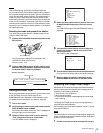
VF attachment shoe
a)
Power supply
for a script light
DC 12 V
(Max. 0.5 A)
Video output
HD-SDI/SD-SDI/VBS
AC power
Intercom headset
Sync input
Return video input
Prompter video input
to router/switcher
(attached to the front)
a) Supplied with the HDVF-550/C730W/C950W, Part No.: A-7612-405-E
b) 600 m (1969 ft) at maximum and 50 m (164 ft) at minimum when using Fujikura 8.5-mm dia. cables.
For information of other cables, see “About the distances of triax transmission” (page 35).
Triax cable
b)
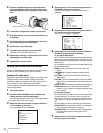
qg
qf qd
qa
0
9
8
qs
5
6
4
2
3
1
7
qh
Note