


7
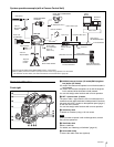
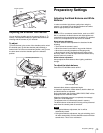
Overview
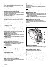
e AUTO W/B BAL (white and black balance automatic
adjustment) switch
To automatically adjust white and black balance when the
camera is used in stand-alone status without connecting to a
CCU.
WHT: To automatically adjust white balance.
BLK: To automatically adjust black balance.
For details, see “Adjusting the Black Balance and White
Balance” (page 13).
f INTERCOM LEVEL control
To adjust the intercom/earphone volume level.
The intercom level adjustment is enabled when the LEVEL/
MIC switch on the UC-type operation panel (page 7) or the
LEVEL switch on the CE-type operation panel (page 8) on the
rear is set to “FRONT.”
g RET (return video) button
When this button is pressed, the picture on the viewfinder
changes to the return video signal selected with the RET 2/3/
4 select switch (page 7) on the operation panel on the rear of
the camera.
You can also assign other functions with a menu operation.
h LENS connector (12-pin)
Connect the lens cable. The camera can control the lens
functions through this cable.
i MIC 1 IN (microphone 1 input) connector (XLR 3-pin)
Connect a microphone.
This connector and the AUDIO IN CH1 connector are
alternately activated with the MIC 1 select switch on the rear
connector panel.
j Tripod mount (bottom)
Attach the VCT-U14 Tripod Adaptor when mounting the
camera on a tripod.
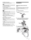
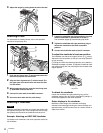
For details, see “Mounting the Camera to a Tripod” (page 12).
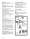
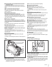
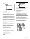
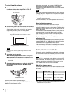
Rear
a Tally lamp and switch
ON: The tally lamp lights when a tally signal is input to the
connected CCU or a call signal is generated in response to
pressing of a CALL button.
OFF: The tally lamp is prevented from lighting.
b Shoulder strap fitting post
c Operation panel (See “Operation panel”.)
d Camera Control Unit (CCU) connector (triax
connector)
Connect an HXCU-100 Camera Control Unit using a triax
cable.
e INTERCOM connector (XLR 5-pin)
Connect an XLR 5-pin headset for input and output of intercom
audio signals.
The connector can be used for communication over the
engineer line when the camera is in standby status.
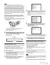
f EARPHONE jack (stereo minijack)
For connecting an earphone for output of the intercom audio.
g Connector panel (See “Connector panel” on page 8.)
h CAMERA POWER switch and indicator
CCU: To operate on power supply via the connected CCU.
EXT: To operate on power supply through the DC IN
connector.
The indicator is lit in green during operation. It is lit in red while
standby power is being supplied from the CCU, even if the
switch is set to OFF.
i CALL button
When you press this button, the red tally lamp of the
connected external control device (RCP/RM, HKCU-FP1, etc.)
will light. Use to call the operator of the external control device.
j Shoulder pad
You can adjust the position on your shoulder.
For details, see “Adjusting the Shoulder Pad Position” (page
13).
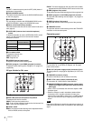
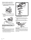
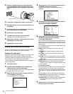
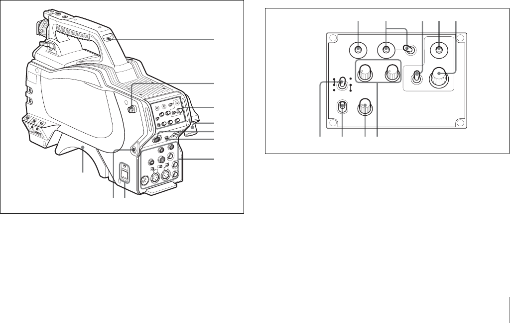
Operation panel
UC type: Model for NTSC areas
a RET 1 (return video 1) button
The return video signal is displayed on the viewfinder screen
while the button is held pressed.
b RET (return video) button and 2/3/4 (return video 2/3/4)
select switch
When other return video systems are used in addition to return
video 1, the signal selected with the 2/3/4 switch is displayed
on the viewfinder screen while holding the RET button
pressed.
7
6
4
1
2
3
5
9
0
8
PGM1
INCOM
PGM2
ASSIGNABLE
234
RET1 RET
PROD
ENG
REAR
ON
OFF
MICLEVEL
FRONT
INTERCOM EARPHONE
DISPLAY
MENU
OFF
12 345
6789