


6
Overview
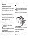
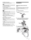
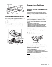
f Lens mount cap
The cap can be removed by moving the lens fixing lever
upward. Always keep the lens mount covered with this cap
when a lens is not attached.
g Lens fixing lever
Move the lever down to secure the lens in the lens mount.
For details, see “Attaching a Lens” (page 10).
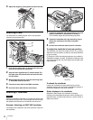
h Viewfinder front-rear position lock lever
The viewfinder position can be adjusted forward or backward
when the lock is released by the lever.
For details on the adjustment, see “To adjust the viewfinder’s
front-rear position” (page 10).
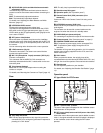
i Assignable buttons
You can assign a function to the upper button by using
ASSIGNABLE 1 and the lower button with ASSIGNABLE 2 on
the <SWITCH ASSIGN1> page of the OPERATION menu.
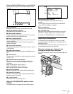
j GAIN switch
To select the gain of the video amplifier based on lighting
conditions when the camera is used in standalone status
without connecting a CCU.
When shipped from the factory, the values set are L = 0 dB,
M = 6 dB, and H = 12 dB.
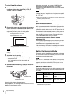
k AUTO KNEE and output signal selection switch
To select the signal (color-bar signal or camera’s video signal)
to be used as output to a VTR, the viewfinder, or a video
monitor when the camera is used in standalone status without
connecting a CCU.
When the camera’s video signal is being used as output, the
auto knee function can be selected.
BARS/OFF: Output is a color-bar signal.
CAM/OFF: Output is the camera’s video signal. The auto knee
circuit is disabled.
CAM/ON: Output is the camera’s video signal. The auto knee
circuit is enabled.
l WHITE BAL (white balance memory selection) switch
To select the white balance adjustment method or the memory
used to store the adjusted value when the camera is used in
standalone status without connecting a CCU.
PRST (preset): White balance is adjusted to a preset value
corresponding to a color temperature of 3200K.
A: To select memory A.
B: To select memory B.
When a CCU or an external control device, such as an RCP/
RM, is connected, the functions of 0 to qs are controlled from
the external device or the HKCU-FP1 attached to the CCU,
and the controls on the camera are disabled.
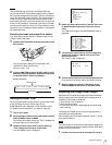
m DISPLAY/MENU switch
Select the display on the viewfinder screen.
DISPLAY: To display various textual information and markers,
such as messages showing the camera settings and
operating status, the center marker, and the safety zone
marker, in addition to camera images.
OFF: To not display textual information and markers.
MENU: To display menus for camera settings.
The switch functions the same as the DISPLAY/MENU switch
on the rear operation panel.
n “Memory Stick” slot and access lamp
When you insert a “Memory Stick” into the slot, the access
lamp lights in green.
The lamp is lit in red while writing/reading data to/from the
“Memory Stick.”
When the access lamp is lit in red, do not insert/remove the
“Memory Stick” or turn off the camera.
o STATUS/CANCEL switch
STATUS: To display status information of this camera in the
viewfinder when no menu is displayed with the DISPLAY/
MENU switch set to DISPLAY.
CANCEL: To cancel changed settings or return the display to
the previous menu when a menu is displayed in the
viewfinder.
p Menu control knob (rotary encoder)
Used to select settings from menus displayed on the
viewfinder screen (by rotating it) and to confirm settings (by
pushing it).
This knob functions the same as that on the rear operation
panel.
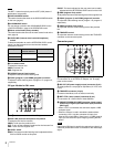
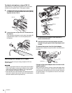
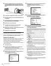
Front left
a Shoulder strap fitting post
Attach one end of a shoulder strap (optional, part No. A-6772-
374-C) to this fitting post and the other end to the fitting post
on the other side of the camera.
b VF (viewfinder) connector (20-pin)
Connect the cable of the viewfinder (optional).
c Filter select knob
Used to select the built-in ND filters (1: clear, 2: 1/4 ND, 3:
1/16 ND, 4: 1/64 ND).
d SHUTTER switch
When the camera is used in standalone status without
connecting a CCU, use this switch to turn ON or OFF the
electronic shutter and change (SEL) the shutter speed and
shutter mode.
For details, see “Setting the Electronic Shutter” (page 14).
Note
Note
9
0
8
1
2
3
4
5
6
7