57RT-PRC005-EN
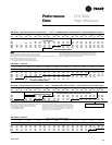
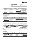
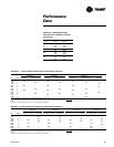
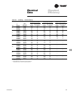
3 Ton 4 Ton 5 Ton
1200 CFM 1600 CFM
1
2000 CFM
Single Phase Three Phase Single Phase Three Phase Single Phase Three Phase
kW Stages T#C036A1 T#C036A3,A4,AW T#C048A1 T#C048A3,A4,AW T#C060A1 T#C060A3,A4,AW TSC060AK
5.00 1 13.2 — 9.9 — 7.9 — —
6.00 1 — 15.8 — 11.9 — 9.5 —
7.50 2 — — — — — — 11.9
10.00 2 26.3 — 19.8 — 15.8 — —
10.90 2 — — — — — — 17.2
12.00 2 — 31.6 — 23.7 — 19.0 —
13.80 2 36.4 — 27.3 — 21.8 — —
14.40 2 — — — — — — 22.8
17.40 2 — 45.8 — 34.4 — 27.5 —
17.60 2 — — 34.8 — 27.8 — —
23.00 2 — — — — — 36.4 —
For minimum design airflow, see airflow performance table for each unit.
To calculate temp rise at different air flow, use the following formula: Temp. rise across Electric Heater =
NOTE:
1. Minimum allowable aiflow with a 17.4 or 17.6 KW heater is 1440 cfm.
Performance
Data
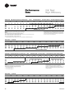
Table PD-76 — 3-5 Tons Air Temperature Rise Across Electric Heaters (Degrees F)
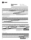
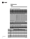
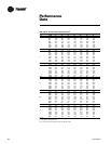
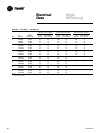
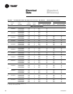
6Ton 7½Ton 8½Ton 10 Ton
2000 CFM 3000 CFM 3400 CFM
1
4000 CFM
T#C090A3, A4, AW
kW Stages T#C072A3, A4, AW TSC072AK T#C092A3, A4, AW TSC090AK T#C102A3, A4, AW TSC102AK T#C120A3,A4,AW TSC120AK
9.00 1 14.2 — 9.5 — 8.4 — — —
11.30 1 — 14.9 — 11.9 — — — —
16.90 2 — 22.3 — 17.8 — 15.7 — 13.4
18.00 1 28.5 — 19.0 — 16.7 — 14.2 —
22.60 2 — 29.8 — 23.8 — 21.0 — 17.9
27.00 2 42.7 — 28.5 — 25.1 — 21.3 —
33.80 2 — — — — — — — 26.7
36.00 2 56.9 — 37.9 — 33.5 — 28.5 —
54.00 2 — — — — — — 42.7 —
For minimum design airflow, see airflow performance table for each unit.
To calculate temp rise at different air flow, use the following formula: Temp. rise across Electric Heater =
NOTE:
1. Minimum allowable aiflow with a 17.4 or 17.6 KW heater is 1440 cfm.
Table PD-77 — 6-10 Tons Air Temperature Rise Across Electric Heaters (Degrees F)
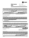
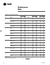
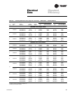
Table PD-75— Electric Heater Voltage
Correction Factors (Applicable to Auxiliary
Heat Capacity)
Nominal Distribution Capacity
Voltage Voltage Multiplier
208 0.751
240 230 0.918
240 1.000
380 380 1.000
440 0.840
480 460 0.918
480 1.000
540 0.810
600 575 0.918
600 1.000
kW x 3414
1.08 x CFM
kW x 3414
1.08 x CFM


