


58
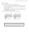
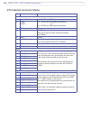
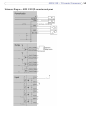
AXIS 233D - I/O terminal Connectors
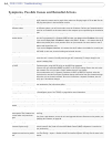
I/O terminal connector blocks
Pin Function Description
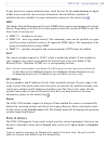
Power/Audio
1 Power AC 18 - 30 VAC max 25VA power consumption.
2 Power
AC/DC+
18 - 30 VAC max 25VA power consumption.
-or-
22 - 40 VDC max 20W power consumption.
3 GND Ground
4 Vout 12V/200mA
Vout can be used to power auxiliary equipment,
max 200mA.
5 GND Ground
6 Line OUT Mono audio output (line level), which can be connected
to an active speaker with built-in amplifier.
7 GND Ground
8 Mic/Line IN Input for a mono microphone or line level mono signal.
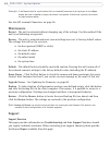
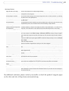
Output
1 Out1_1_relay On the external device output terminals (e.g. Out1_1 and
Out1_2) there is no distinction between positive and neg-
ative. The terminals use a photocoupler and are electri-
cally isolated from the other internal circuitry.
The maximum load should not exceed 500mA and the
maximum voltage should be not more than 50VDC or
35VAC.
2 Out1_2_relay
3 Out2_1_relay
4 Out2_2_relay
5 Out3_1_relay
6 Out3_2_relay
7 Out4_1_relay
8 Out4_2_relay
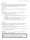
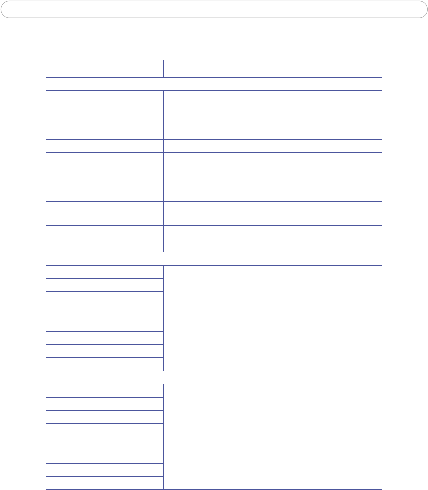
Input
1 In1_anode(+) Electrically isolated from the chassis and connectors,
these inputs can be supplied from an external DC voltage
or pin 4 (Vout) of the Power/Audio Connector and GND.
(3.3 - 40VDC allowed on the inputs)
The terminals use a photocoupler and are electrically iso-
lated from the other internal circuitry.
Note: There is a distinction between anode and cathode
when making connections!
2 In1_cathode(-)
3 In2_anode(+)
4 In2_cathode(-)
5 In3_anode(+)
6 In3_cathode(-)
7 In4_anode(+)
8 In4_cathode(-)