


MIC Series 550 Camera Installation | en 21
Bosch Security Systems, Inc. User Manual F.01U.239.454 | 3.0 | 2012.09
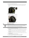
5.6 Electrical Connections
All connections (power, telemetry, video) to the camera are provided through the screw
terminal connections in the MIC power supply. Purpose-built composite cables, available in
various lengths, are 2-conductor cables that are pre-made with a female terminated 12-way
connector fitted to them for attachment to the male connector installed into the base of the
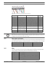
camera. The table below identifies the available lengths of these cables, which are required
but sold separately from the camera. (The gauge ranges from 14 - 18.)
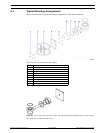
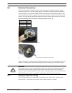
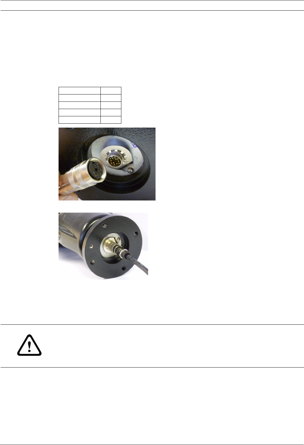
Figure 5.8 Composite cable before connection
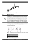
Figure 5.9 View of the Composite Cable connected to a MIC Series 550 camera
Refer to the MIC Series Power Supply Installation Manual included on the Installation CD for full
details on installing a MIC Series Power Supply Unit and connecting to a MIC-550 Camera.
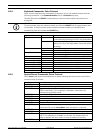
5.6.1 Composite Cable Color-coding
The composite cable has no termination (free wires) at the other end for wiring into the
power supply. The standard color coding used in these cables is as follows:
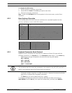
Model Number Length
MIC-2MS 2 m
MIC-10MS 10 m
MIC-20MS 20 m
MIC-25MS 25 m
WARNING!
Ensure that all power is disconnected before opening or working on the MIC power supply.
Installation should be made by qualified service personnel and conform to the National
Electrical Code and applicable local codes. Ensure a strong safety chain is used to secure the
MIC-550 Camera to prevent any danger of dropping the product during installation.