


22 en | Installation MIC Series 550 Camera
F.01U.239.454 | 3.0 | 2012.09 User Manual Bosch Security Systems, Inc.
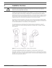
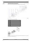
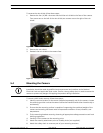
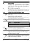
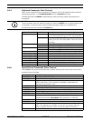
Figure 5.10 Exploded View of Composite Cable Connections
* Note: Half-duplex is 2-wire operation. Full-duplex is 4-wire operation.
5.6.2 Alarm Inputs and Outputs
The table below identifies the number of alarm inputs and outputs available depending on the
type of MIC power supply unit installed and whether or not an 8-input alarm card is installed.
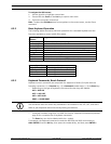
Table 5.1 Number of alarm inputs and outputs by power supply unit (PSU)
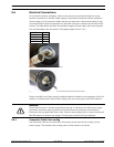
5.6.3 Video
The video coax cable should use a shield coverage copper braid 95% and standard copper
center conductor. Recommended cables are RG-59, RG-6/U, or RG-11U.
Camera Cable
Connector Pin
Signal Name Description Cable Wire
Color
1 Washer Drive Rtn Auxiliary Connection Grey
2 Tamper Sw Rtn Auxiliary Connection Brown
3 Washer Drive Wash Signal Orange
4 Tamper Sw Alarm Communications Black
5 Video Return Video Signal Ground Coax Screen
6 Video Output Video Output to Control Room Coax Core
7 Full Duplex Tx B Telemetry I/O to RS-422/485 Violet
8 Full Duplex Tx A Telemetry I/O to RS-422/485 Blue
9 0v Ground Shield
10 Full Duplex Rx A (-)
Half Duplex* Tx/Rx A (-)
Telemetry I/O to RS-422/485 Yellow
11 Full Duplex Rx B (+)
Half Duplex* Tx/Rx B (+)
Telemetry I/O to RS-422/485 White
12 Power Input 2 Low Voltage Power Input Green
13 Power Input 1 Low Voltage Power Input Red
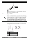
NOTICE!
Bosch does not recommend using the shielded composite cable for distances in excess of 25
m between the camera and the MIC power supply.
Type of MIC Power Supply Unit Number of Alarm Inputs Number of Alarm Outputs
IR 4 0
Non-IR with 8-input alarm card 8 2
Non-IR without alarm card 1 0
Cable Type Maximum Distance
RG-59/U 300 m (1000 ft)
RG-6/U 450 m (1500 ft)
RG-11/U 600 m (2000 ft)
Size O.D. between 4.6 mm (0.181 in.) and 7.9 mm (0.312 in.)
Shield Copper braid: 95%
Central Conductor Standard copper center
Terminal Connector BNC