


18 en | Installing the Pendant Arm Wall, Corner, and Mast (Pole) Mounts AutoDome 800 Series HD PTZ Camera
F.01U.273.797 | 5.0 | 2012.08 Installation Manual Bosch Security Systems, Inc.
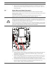
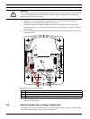
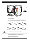
4. Attach the supplied 3-pin Power Plug to the incoming power wires. See connector P101
in Table 2.1, Page 20, for wire connections.
5. Attach an RJ45 plug to the incoming Ethernet cable. If installing a Fiber Optic model,
attach an ST fiber plug to the optic fiber cable. See Section 4 Cable and Wire Standards,
page 51, for the different methods of transmitting video and control protocols, and wire
specifications.
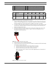
6. If you are connecting alarm inputs and relay outputs, attach the supplied 4-wire Alarm
Output and the 6-wire Alarm Input flying leads to the appropriate relay and alarm wires.
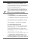
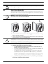
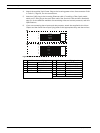
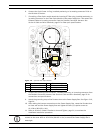
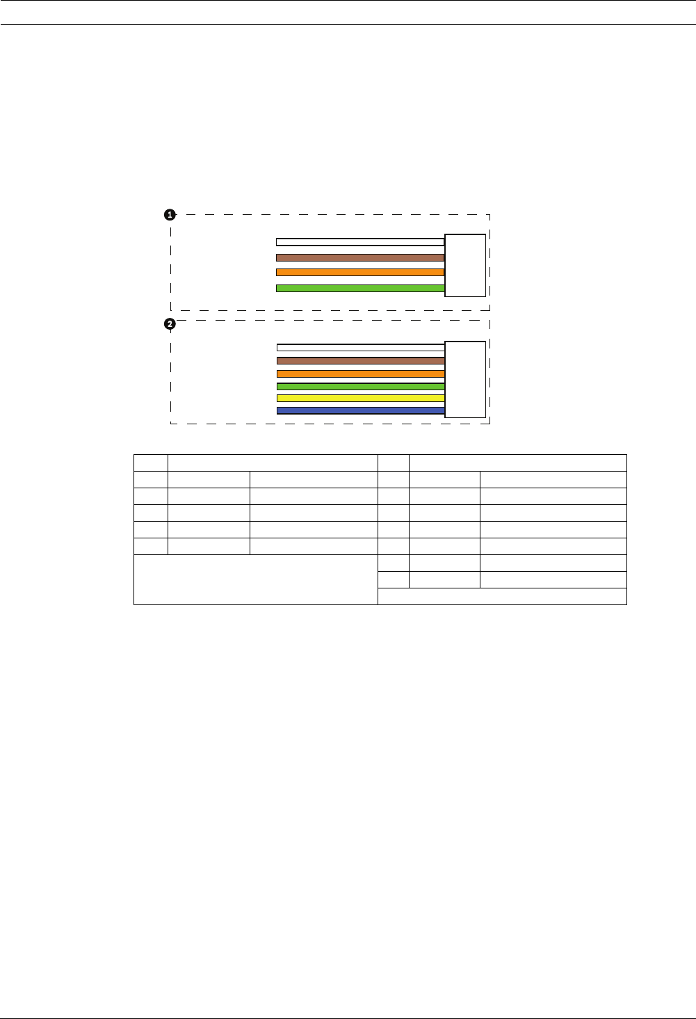
Figure 2.3 Alarm and relay connectors
1 4-pin Alarm Output Flying Lead 2 6-pin Alarm Input Flying Lead
Wire Color Description Wire Color Description
1 White Not used 1 White Alarm Input 1 (A3)
2 Brown Not used 2 Brown Alarm Input 2 (A4)
3 Orange Relay Out 1 3 Orange Not used
4 Green Relay Ground 4 Green Not used
5 Yellow Not used
6 Blue Alarm Ground (AGND)
1
1
2
3
4
5
6
2
3
4
WIRE
WIRE
WHITE
ORANGE
BROWN
GREEN
WHITE
ORANGE
BROWN
GREEN
YELLOW
BLUE