


34 en | Installing Roof Parapet and Pipe Mounts AutoDome 800 Series HD PTZ Camera
F.01U.273.797 | 5.0 | 2012.08 Installation Manual Bosch Security Systems, Inc.
3.2 Pre-installation Check List
1. Determine the location and distance for the power supply box based on its voltage and
current consumption. See Section 4 Cable and Wire Standards, page 51 for wiring
information and distances.
2. Use only UL listed liquid tight strain reliefs for conduits to the Power Supply Box to
ensure that water cannot enter the box. You must use water tight conduits and fittings to
meet NEMA 4 standards.
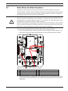
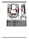
3. Install all rough wiring including: power, Ethernet, alarms I/O, relay I/O, and fiber optic
cabling. See Section 4 Cable and Wire Standards, page 51 for video and control protocol
methods.
4. Choose the appropriate AutoDome model for the environment in which it will be used.
5. Choose the appropriate mounting kit to use depending on the location of the AutoDome:
Parapet (Roof) mount or the Pipe mount.
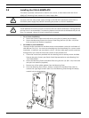
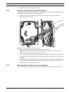
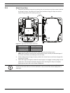
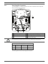
3.3 Mount Power Supply Box
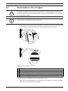
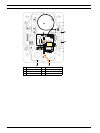
Before mounting the Power Supply Box decide if you will be wiring the box through the holes
in the bottom or back of the box. If wiring the box through the back, move the two (2) seal
plugs to the bottom holes before mounting.
NOTICE! Power and I/O cabling must be routed separately inside different permanently
earthed metal conduits.
WARNING!
External interconnecting cables are to be installed in accordance to NEC, ANSI/NFPA70 (for
US application) and Canadian Electrical Code, Part I, CSA C22.1 (for CAN application) and in
accordance to local country codes for all other countries.
Branch circuit protection incorporating a 20 A, 2-pole Listed Circuit Breaker or Branch Rated
Fuses are required as part of the building installation. A readily accessible 2-pole disconnect
device with a contact separation of at least 3 mm must be incorporated.
CAUTION!
Select a rigid mounting location to prevent excessive vibration to the AutoDome camera.
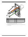
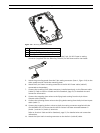
NOTICE! Use 3/4-inch NPS (20-mm) fittings for the holes on the bottom and back of the box.
Use 1/2-inch NPS (15-mm) fittings for the side holes. See Section 3.1.1 Parts List, page 33, for
an illustration.