


AutoDome 800 Series HD PTZ Camera Installing the Pendant Arm Wall, Corner, and Mast (Pole) Mounts | en 21
Bosch Security Systems, Inc. Installation Manual F.01U.273.797 | 5.0 | 2012.08
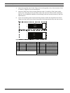
To properly wire the incoming high voltage and the outgoing low voltage lines, refer to this
table:
Table 2.2 VG4-PSU1/VG4-PSU2 Power Supply Box Connections
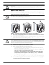
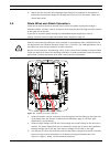
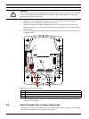
1. Route the high voltage 115/230 VAC lines through the conduit fitting on the left side of
the box. The Power Supply Box with a transformer comes with a barrier that separates
the high voltage side on the left, from the low voltage 24 VAC side on the right.
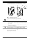
2. Cut and trim the high voltage 115/230 VAC power and ground wires with sufficient slack
to reach their connector terminal in the box, but not so long as to be pinched by or to
obstruct closing the cover door.
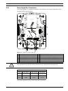
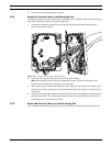
3. Attach the supplied 3-pin power plug to the incoming high voltage power wires in the
box. Refer to connector P101 in Table 2.2, Page 21 and to the image below for an
illustration of these connections:
Figure 2.6 Incoming 115/230 VAC power supply
4. Attach the ground wire to the grounding screw.
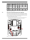
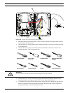
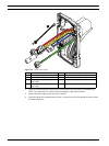
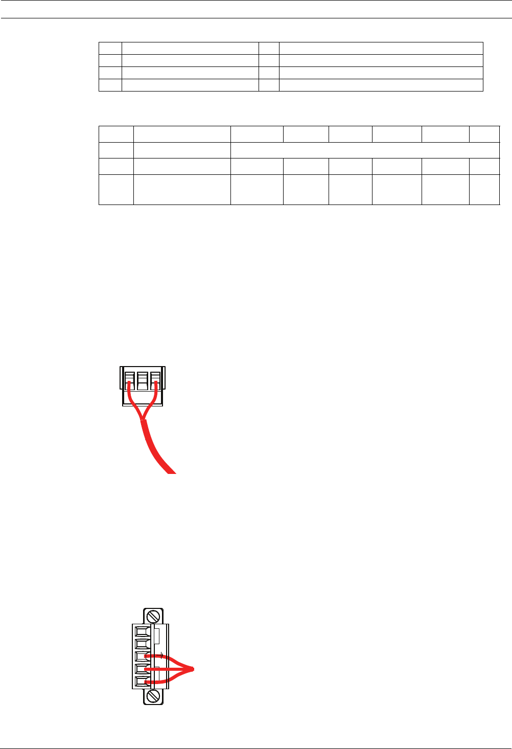
5. Connect three wires to the P107 Power Out connector to route the 24 VAC power supply
to the VG4-PA0 Power Supply Box.
a. Connect the first wire to pin 5 (HN: Heater Neutral) connector.
b. Connect the second wire to pin 4 (HL: Heater Line) connector.
c. Connect the third wire to pin 3 (Earth Ground) connector.
Refer to connector P107 in Table 2.2 and to the image below for an illustration of
these connections:
Figure 2.7 Outgoing 24 VAC power supply
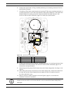
1 120/230 VAC Power In 5 Transformer
2 Ground Wire 6 In/Out Conduit (1/2 in. [15 mm] NPS Fitting
3 P101 Connector 7 24 VAC Power Out to VG4-PA0
4 P107 Connector
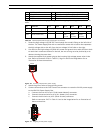
No. Connector Pin 1 Pin 2 Pin 3 Pin 4 Pin 5 Pin 6
Ground Grounding Screw
P101 115/230 VAC Power In Line NC Neutral
P107 24 VAC Power
Out Earth
Ground
Heater
(24 VAC)
Heater
(24 VAC)
P101
24V NC 24V
1 2 3
P107
5 4 3 2 1
HTR DOME