


48 en | Installing Roof Parapet and Pipe Mounts AutoDome 800 Series HD PTZ Camera
F.01U.273.797 | 5.0 | 2012.08 Installation Manual Bosch Security Systems, Inc.
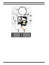
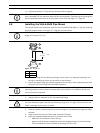
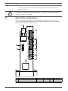
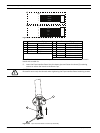
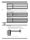
Figure 3.11 Alarm and Relay Connector Plugs
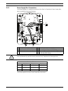
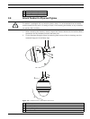
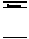
Note: There is a slot located at the top of the Interface Board to tie the wires to the circuit
board with a cable tie.
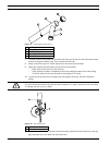
5. Insert the Pipe Interface Board into the down pipe and fasten the three (3) retaining
screws to secure the board to the Dome Cap.
Figure 3.12 Pipe Interface Board to Dome Cap Assembly
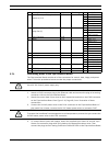
1 4-pin Alarm Output Flying Lead 2 6-pin Alarm Input Flying Lead
Wire Color Description Wire Color Description
1 White Not used 1 White Alarm Input 1 (A3)
2 Brown Not used 2 Brown Alarm Input 2 (A4)
3 Orange Relay Out 1 3 Orange Not used
4 Green Relay Ground 4 Green Not used
5 Yellow Not used
6 Blue Alarm Ground (AGND)
1
1
2
3
4
5
6
2
3
4
WIRE
WIRE
WHITE
ORANGE
BROWN
GREEN
WHITE
ORANGE
BROWN
GREEN
YELLOW
BLUE
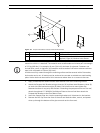
CAUTION!
Be careful not to strip the threads when tightening the Pipe Interface Board retaining screws.