


AutoDome 800 Series HD PTZ Camera Installing the Pendant Arm Wall, Corner, and Mast (Pole) Mounts | en 25
Bosch Security Systems, Inc. Installation Manual F.01U.273.797 | 5.0 | 2012.08
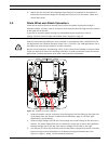
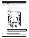
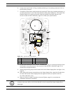
6. Connect the 3-pin Power In Plug, installed previously, to its matting connector P101 on
the left side of the box.
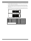
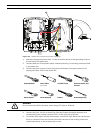
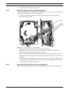
7. If installing a Fiber Optic model attach the incoming ST fiber plug, installed previously, to
its mating connector on the Fiber Optic Module in the power supply box. Then attach the
Ethernet cable to its mating connector from the Pendant Connector Harness. See
Section 4 Cable and Wire Standards, page 51 for fiber optic specifications.
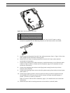
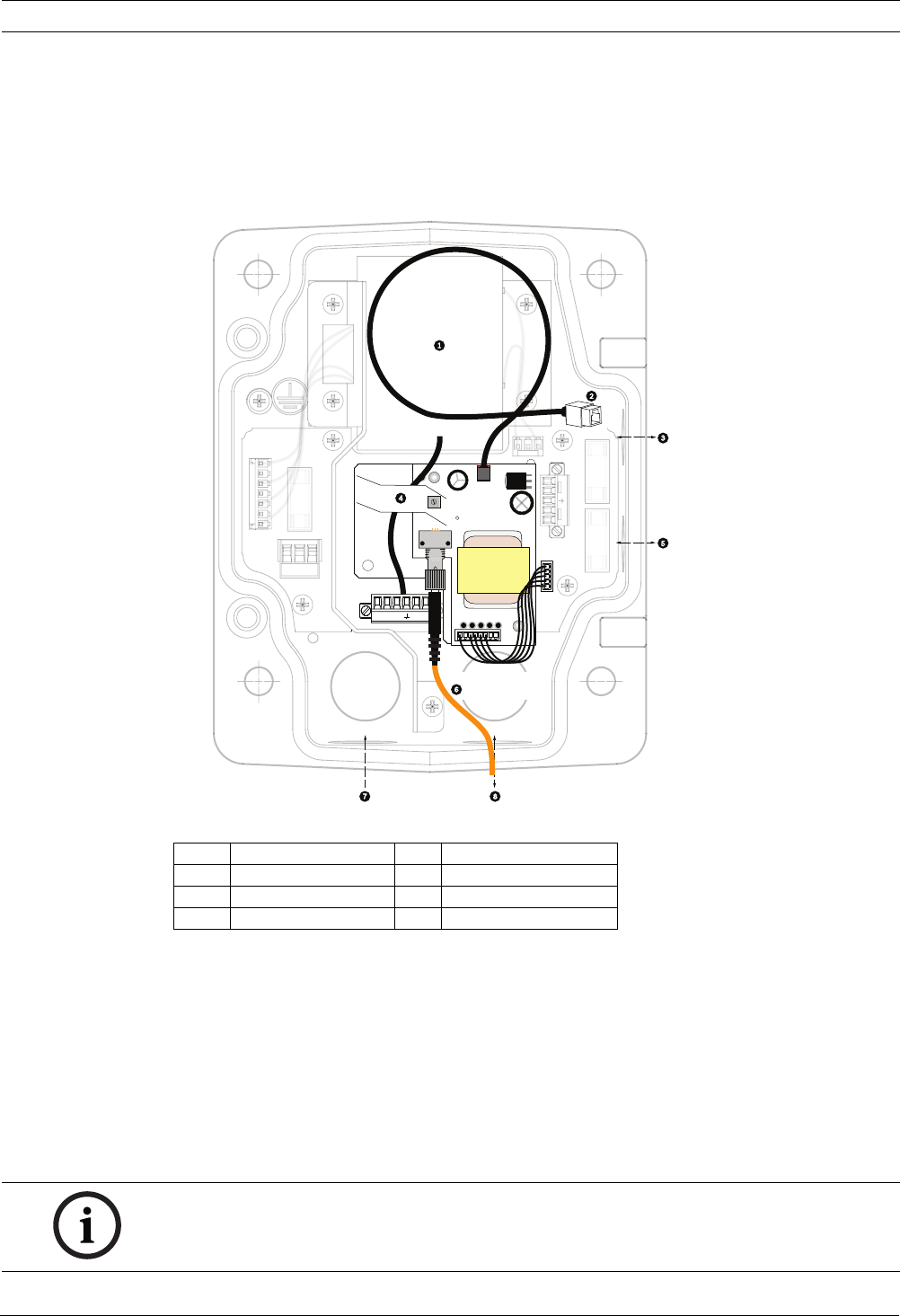
Figure 2.11 Optional Fiber Optic Module
8. Connect the incoming RJ45 connector, installed previously, to its mating connector from
the Pendant Connector Harness. See Section 4 Cable and Wire Standards, page 51 for
connections and specifications.
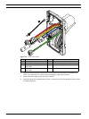
9. Attach the grounding strap of the Pendant Arm to the Power Supply Box. See Figure 2.10,
Page 24.
10. After making the harness connections to the Power Supply Box, rotate the Pendant Arm
to close and seal the Power Supply Box and tighten the two (2) captive screws to
10-12 N-m (90-105 in.-lbs).
11. Refer to Section 2.9 Attach Pendant to Arm and Tighten, page 31, to continue the
AutoDome Installation procedure.
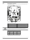
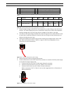
1 Transformer 5 In/Out
2 Ethernet to Dome 6 ST Connector (Fiber)
3In/Out 7Power In
4 From Arm Harness 8 Data In/Out
(GND)
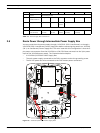
GND TXD
RXD
C+
C-
(
FUSE)
(
FUSE)
(
FUSE
)
24V N
C
24
V
HTR DOME
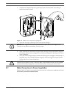
NOTICE! After all wiring is complete, close the cover door and tighten the two (2) captive
screws on the cover door to 10-12 N-m (90-105 in.-lbs) to ensure the Power Supply Box is
watertight.