


AutoDome 800 Series HD PTZ Camera Installing Roof Parapet and Pipe Mounts | en 47
Bosch Security Systems, Inc. Installation Manual F.01U.273.797 | 5.0 | 2012.08
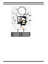
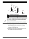
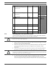
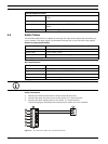
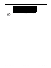
3.7.1 Connecting Wires to the Pipe Interface Board
The Pipe Interface Board contains all of the connectors for control, data, image, and power
wires. Follow the procedures below to make the proper connections.
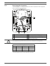
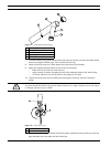
1. Attach an RJ45 connector plug to the Ethernet cable and connect the plug to its mating
connector J101 on the Pipe Interface Board.
2. Attach the control data in/out wires to their respective terminals on the P105 connector
on the Pipe Interface Board. See Figure 3.10, Page 46, for an illustration of these
connections.
3. Connect the 24 VAC power wires to the P101 connector on the Pipe Interface Board. If
this model has a heater, connect the 24 VAC heater power wires to connector P107.
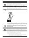
4. To connect alarm inputs and outputs, attach the supplied 6-pin Alarms In and the 4-pin
Alarms Out connector plugs with flying leads to the appropriate alarm wires. Then
connect the plugs to their mating connectors P103 and P102 on the Pipe Interface Board.
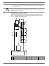
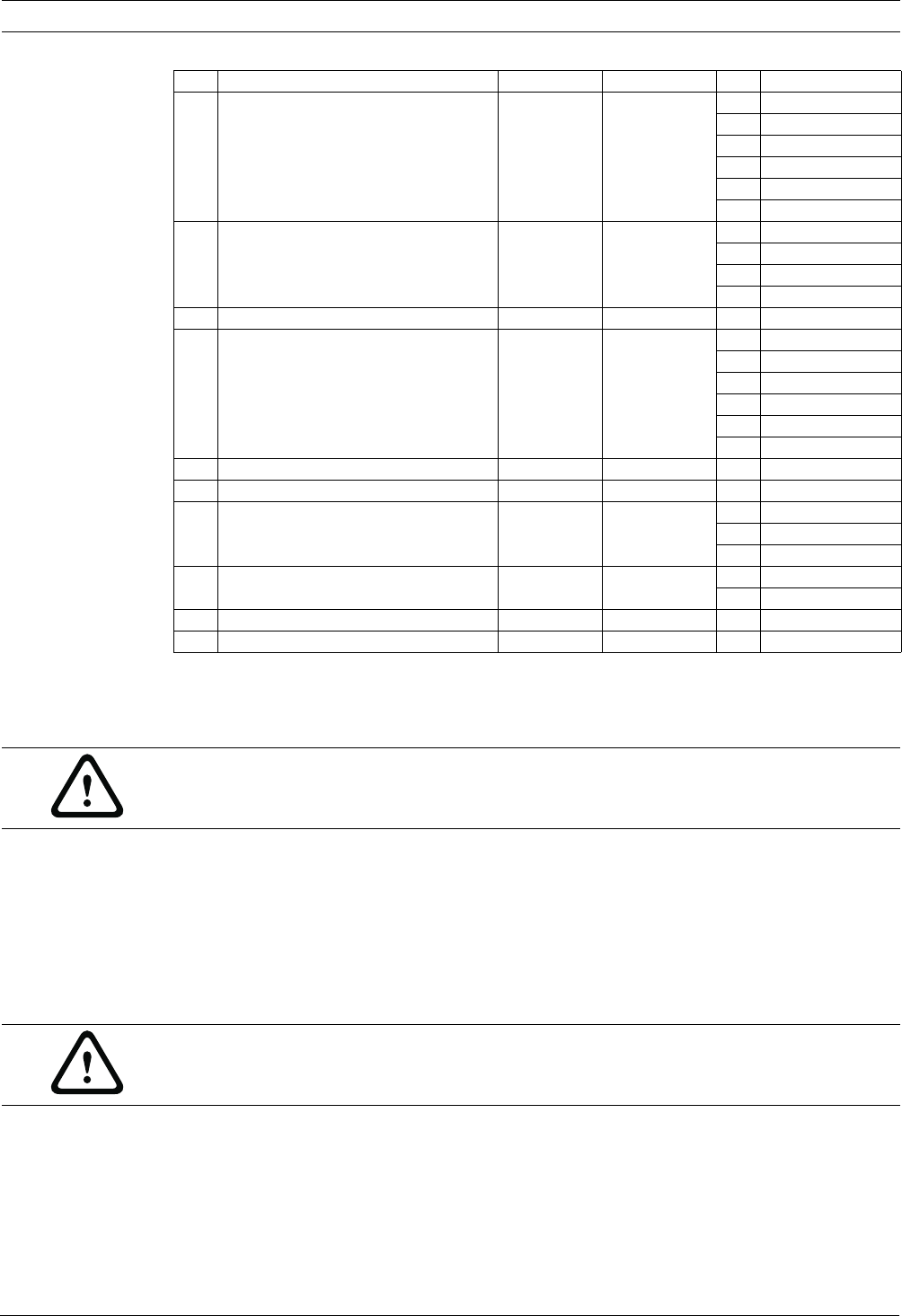
3 6-pin Alarm Input Flying Lead
Alarms In (1-2)
P103 1 Alarm In 1
2 Alarm In 2
3Not used
4Not used
5Not used
6Alarm Ground
4 4-pin Alarm Outputs Flying Lead
Relay Out (1)
P102 1 Not used
2Not used
3 Relay Out 1
4Relay Ground
5 100 Ω Resistor P105
6 Audio P105 1 Audio- (C-)
2 Audio+ (C+)
3NC
4NC
5NC
NC
7 Not Used P104
8 Not Used P104
9 Dome Power P101 AWG 18-14 3 Dome 24 VAC
2 Earth Ground
1Dome 24 VAC
10 Heater Power P107 AWG 18-14 2 Heater 24 VAC
1 Heater 24 VAC
11 RJ45 Ethernet Video and Control J101
12 To AutoDome
Ref. Description Connector Wire Gauge Pin Description
WARNING!
Use a 24 VAC Class 2 power supply only.
CAUTION!
To protect the AutoDome from damage due to cold temperatures, ensure that you connect the
24 VAC heater power wires to the P101 connector.