


AutoDome 800 Series HD PTZ Camera Installing the Pendant Arm Wall, Corner, and Mast (Pole) Mounts | en 19
Bosch Security Systems, Inc. Installation Manual F.01U.273.797 | 5.0 | 2012.08
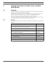
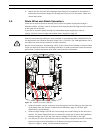
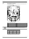
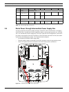
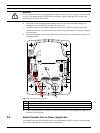
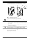
2.4.1 Power Supply Box Connections
The following figure is a detailed illustration of the Pendant Arm Power Supply Box, which
includes the fuse specifications.
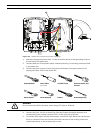
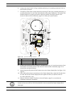
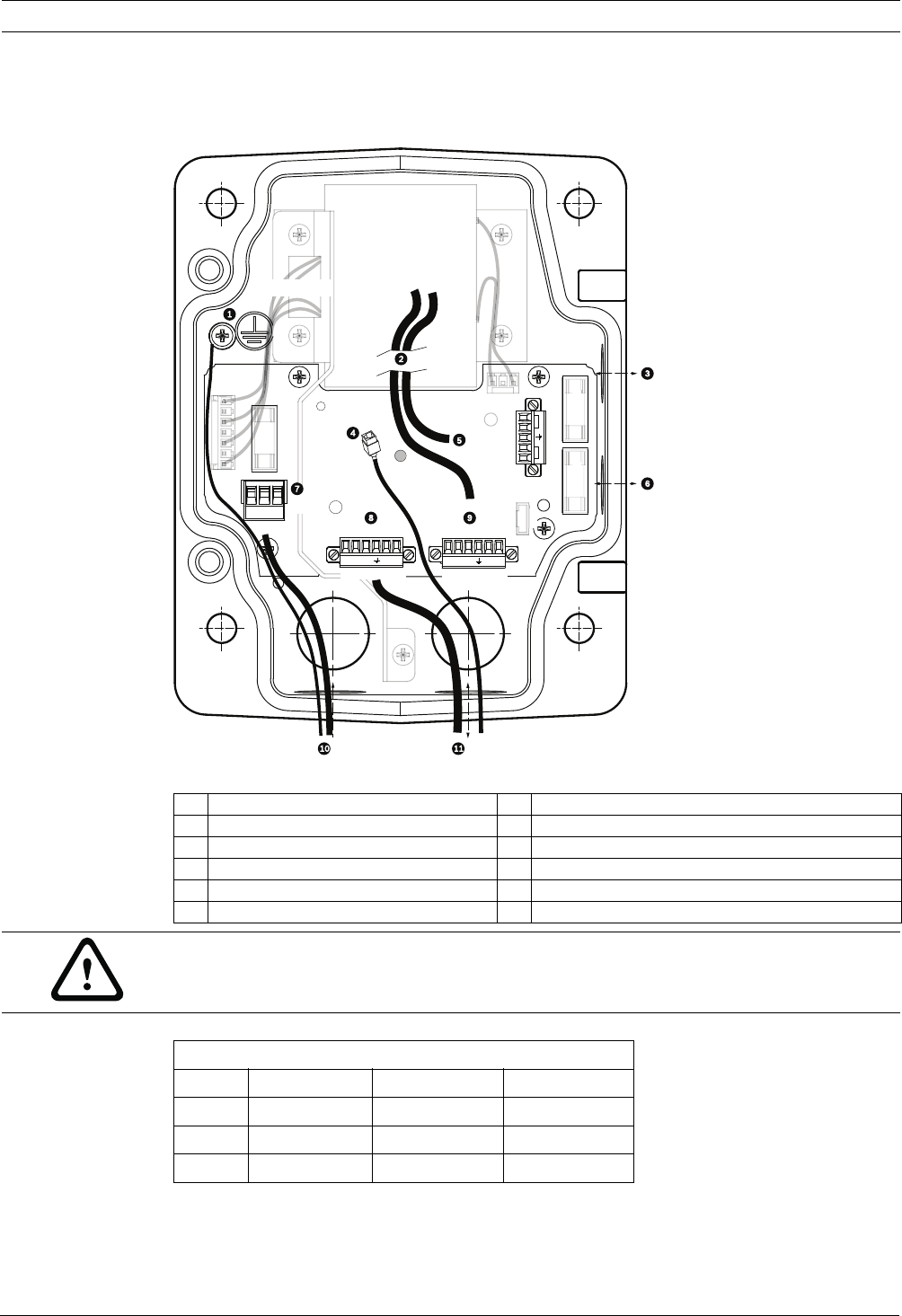
Figure 2.4 Pendant arm power supply box
The following table lists the Power Supply Box connectors:
1 Ground Screw 7 P101 Connector; Power In
2 From Harness 8 P106 Connector; Audio In
3 In/Out; 1/2 in. (15 mm) NPS Fitting 9 P105 Connector; Audio In to Dome
4 Ethernet (video and control) 10 Power In; 3/4 in. (20 mm) NPS Fitting
5 24 VAC to Dome 11 Audio In; 3/4 in. (20 mm) NPS Fitting
6 In/Out; 1/2 in. (15 mm) NPS Fitting
TRAN
S
F
O
RMER
(115/230VAC
MODELS
)
P101
1 2 3
6 5 4 3 2 1 6 5 4 3 2 1
P106
XF102 XF103
XF101
J103
J103
J
J103
J
1
0
2
1
1
1
1
1
1
1
1
1
1
1
1
1
1
1
1
1
1
1
1
1
1
J1
0
1
1
1
1
1
1
1
1
1
1
1
1
1
1
1
(LED)
P107
5 4 3 2 1
GND TXD
RXD
C+
C-
P105
GND TXD
RXD
C+
C-
HTR DOME
(FUSE)
(FUSE)
)
)
)
)
(FUSE
)
24V NC 24V
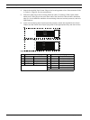
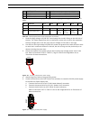
WARNING!
Fuse replacement by qualified service personnel only. Replace with same type fuse.
Fuse Specifications
Volts XF101 Mains XF102 Camera XF103 Heater
24 V T 5.0 A T 2.0 A T 3.15 A
115 V T 1.6 A T 2.0 A T 3.15 A
230 V T 0.8A T 2.0 A T 3.15 A