


1-4
Cisco Video Surveillance 2500 Series IP Camera User Guide
OL-19273-02
Chapter 1 Overview
IP Camera Physical Details
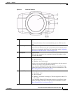
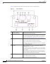
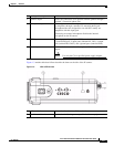
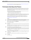
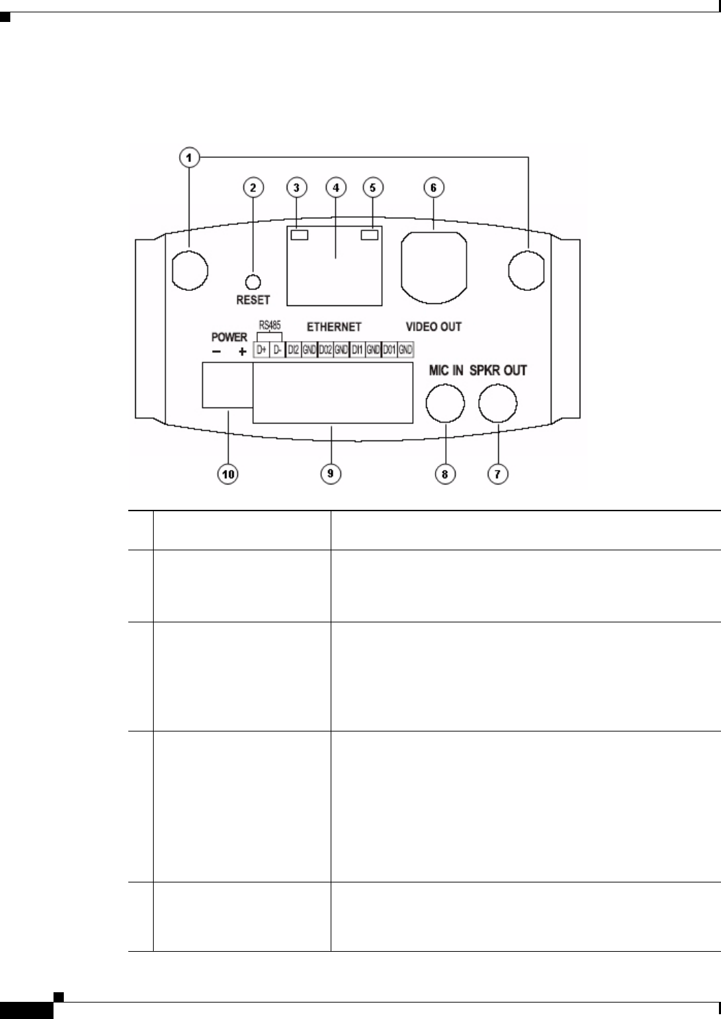
Figure 1-2 and the table that follows describe the items on the rear of the IP camera.
Figure 1-2 Rear of IP Camera
1 Antenna connectors
(wireless model only)
Antennas screw into these connectors and are used for
communication in wireless networks.
2 Reset button Recessed button that reboots the IP camera or resets it to a default
state. You can use a pin or paper clip to depress it. It can be used
any time that the IP camera is on and can have various effects, as
described in the
“Resetting the IP Camera” section on page 2-9.
3 Network LED (amber) Indicates information about the network connections as follows:
• On—LAN or wireless connection is detected
• Off—LAN or wireless connection is not detected
• Blinking—Data is being transmitted or received via the LAN
or wireless connection
4 LAN port Accepts a standard LAN cable to connect the IP camera to a
10/100BASETrouter, or switch.
On the wireless IP camera model, attaching a LAN cable disables
the wireless interface. Only one interface, wired or wireless, can be
active at a time.
Connect or disconnect the LAN cable only when the IP camera is
powered off. Doing so while the IP camera is powered on does not
switch the interface between wired and wireless.
5 PoE LED (green) Indicates information about PoE as follows:
• On—PoE connection is detected
• Off—PoE connection is not detected