


1-5
Cisco Video Surveillance 2500 Series IP Camera User Guide
OL-19273-02
Chapter 1 Overview
IP Camera Physical Details
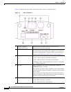
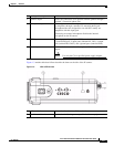
Figure 1-3 and the table that follows describe the items on the side of the IP camera.
Figure 1-3 Side of IP Camera
6 Analog video output BNC connector for video output (75 ohm).
7 Speaker output Allows the connection of an optional external speaker through a
standard 3.5 mm mini phone jack.
8 Microphone input Allows the connection of an optional external microphone (with
pre-amplifier) through a standard 3.5 mm mini phone jack.
Microphones that are designed for use with PCs usually are
compatible with this input jack.
Connecting an external microphone disables the internal
microphone on the IP camera.
9 GPIO ports General purpose input/output (GPIO) terminal block that includes
a 2-pin RS-485 port, 2 input ports (labeled DI1, DI2), 2 output
ports (labeled DO1, DO2), and 4 ground ports (labeled GND).
10 Power input Provides for the connection of an optional 12 V, 1 amp DC power
adapter.
Caution Use only the Cisco specified power supply adapter.
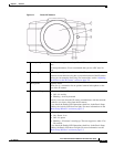
1 DC auto iris lens connector Connection for cable from DC auto iris lens
2 Lockdown cable slot Connection for Kensington-compatible lockdown equipment