


iDP3210 User’s Manual
31
CITIZEN
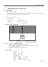
7. DRAWER KICKOUT CONNECTOR
7.1 Specifications
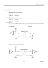
(1) Drawer-Kick Drive Signal
Pulses specified by ESCp are output. Also, SW(+) state, in parallel interface, can be observed by Pin 34 of
the interface connector and, in serial interface, by ESC u command.
(2) Electrical Characteristics
1) Drive voltage : DC24V
2) Drive current : Max. 0.8A (within 510ms)
3) SW signal : signal level "L"= 0 ~ 0.5V
"H"= 3 ~ 5V
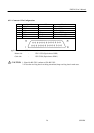
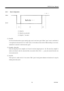
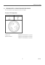
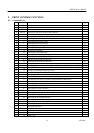
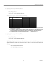
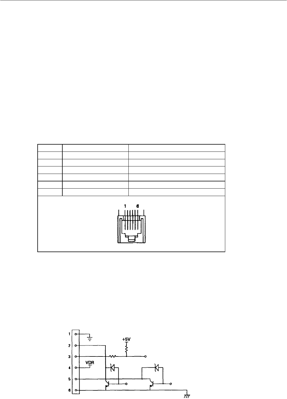
7.2 Connector’s Pin Configurations
No. Signal Name Function
1 FG Frame ground
2 DRAWER 1 Drawer 1 driving signal
3 DRSW Drawer SW input
4 VDR Drawer driving power supply
5 DRAWER 2 Drawer 2 driving signal
6 GND Common ground on the circuits
Connector used : TM5RJ3-66 (Hirose) or equivalent
Applicable connector : TM3P-66P (Hirose) or equivalent
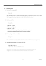
[Caution] 1) No output is available during printing.
2) Drawer 1 and Drawer 2 can not be driven simultaneously.
3) Use a solenoid of 36Ω or more for the drawer. Do not exceed 0.8A for output current.
Failure or seizure can take place.
4) No connection is available to a to a telephone line.
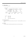
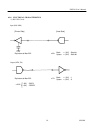
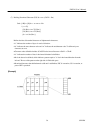
7.3 Drive Circuit