


iDP3210 User’s Manual
43
CITIZEN
(22) Generating specified Pulse (ESC p m n1 n2)
Code : [1B]h + [70]h + m + n + n2
* {m = connector pin No. (See table below.)}
{0 ≤ n1 ≤ FF}
{0 ≤ n2 ≤ FF} Data is described in Hex code.
•Signals specified by n1, n2 are output to Connector Pin m.
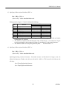
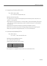
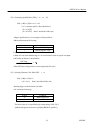
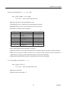
•Bit m (m0) means the followings.
m0 Condition
0 Drawer kick No. 2 pin
1 Drawer kick No. 5 pin
• ON time is considered as n1 x 2ms and OFF time as n2 x 2ms.
• When m is out of the defined range, n1, n2 are discarded, where no signals are output.
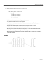
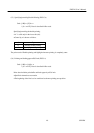
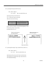
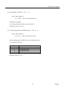
• Drive duty of Drawer is shown below:
(Take OFF time as being 4 times or more longer than ON time.)
(23) Selecting Character Code Table (ESC t n)
Code : [1B]h + [74]h + n
*{0≤ n ≤ 1} Data is described in Hex code.
Selecting Page n on the character code table:
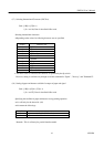
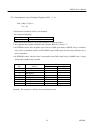
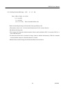
•"n" means the followings.
n (Hex) Condition
0 IBM Character #2
1 Japanese Character
The initial value of n is specified by dip switch setting. (DS1-5.6.7)
(Other than Japanese character is specified, IBM #2 is specified.)
ON Time
On Time + OFF Time