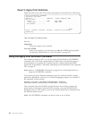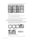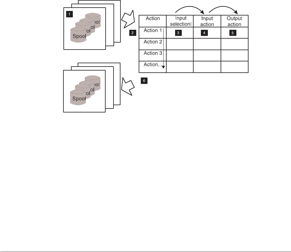
Figure 94 diagrams the sequence in which the APU Monitor processes the action
groups.
Here is an explanation of the steps shown in the diagram:
1. The monitor is invoked each time a spooled file arrives in a monitored output
queue or if the spooled file status from a spool in a monitored queue changes
to *RDY. Spooled files with other status conditions are not processed.
2. The monitor checks the input selection from each action rule in a sequential
manner.
3. As soon as a spooled file matches the action input selection, the input and
output action are performed. Subsequent actions are ignored.
4. The input action is applied after the selection matches a spooled file. The action
performed depends on whether or not APU is able to complete the job
successfully.
5. You can define up to 16 output actions. This allows you, for example, to use
several different APU print definitions for the same spooled file.
6. One or more spooled files are placed into one or more output queues.
An Example of APU Monitor Processing
This section describes an example of how the concepts of the APU Monitor can be
implemented in a customer environment.
A Customer Environment
Assume that a customer wants to set up the following environment:
v Three different output types are needed. with each going to a different output
queue (OUTQs).
v Two printers are available, and the monitor is to be set up with the following
requirements:
– System output (QSYSPRT) must not use an APU print definition.
– All jobs in OUTQ1 must be sent to PRT01
– All jobs in OUTQ2 and OUTQ3 must be sent to PRT02
– Application jobs APP01 and APP02 must be sent with a print definition
SAMPLE applied
Figure 94. APU Monitor Processing Sequence
84 APU User’s Guide


