


EN59
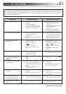
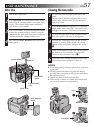
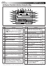
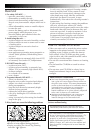
Controls
1 Flash Switch [FLASH OPEN] ................ ੬ pg. 22
2 Dioptre Adjustment Control ................. ੬ pg. 11
3 Battery Release Button
[BATT. RELEASE] .................................... ੬ pg. 7
4 •MENU dial [+, –, PUSH] ................... ੬ pg. 18
•LCD Monitor BRIGHT
(Brightness) Control [+, –] .................. ੬ pg. 12
5 •Power Zoom Lever [T/W] .................. ੬ pg. 14
•Speaker/Headphone Volume Control
[VOL.] .............................................. ੬ pg. 31
6 Snapshot Button [SNAPSHOT] ............. ੬ pg. 16
7 OPEN/EJECT Switch ............................... ੬ pg. 9
8 Snapshot Mode Button
[SNAP MODE] .................................... ੬ pg. 16
9 MULTI SCREEN Button ........................ ੬ pg. 17
0 BACKLIGHT Button ............................. ੬ pg. 29
! Monitor Open Button [PUSH OPEN] ... ੬ pg. 12
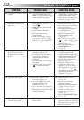
@ Play/Pause Button [
4
/6]...................... ੬ pg. 31
# Stop Button [5] ................................... ੬ pg. 31
$ Fast-Forward Button [
3
] .................... ੬ pg. 31
% Rewind Button [
2
] ............................ ੬ pg. 31
^ Power Switch
[ , , , 5S, OFF] ...................... ੬ pg. 12
& Recording Start/Stop Button.................. ੬ pg. 12
* Lock Button ......................................... ੬ pg. 12
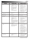
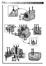
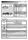
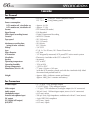
Connectors
The connectors ( to q are located beneath a cover.
( Headphone Connector [PHONE] ......... ੬ pg. 50
) External Stereo Microphone Input Connector
[MIC] .................................................. ੬ pg. 50
q Audio/Video Output Connector
[AV] .................................. ੬ pg. 34, 35, 38, 45
To connect cables to the following connectors w to
t, open the LCD monitor.
w Digital Video Connector [DV OUT]
(i.link*) .................................... ੬ pg. 36, 37, 39
* i.Link refers to the IEEE1394-1995 industry
specification and extensions thereof. The logo
is used for products compliant with the i.Link
standard.
e J Terminal/Edit Connector [JLIP (Joint Level
Interface Protocol) (EDIT)] .................... ੬ pg. 45
•Connect the editing cable when performing
Random Assemble Editing.
•Connect to a JLIP-compatible camcorder or VCR
to control it from the computer using the
provided Software.
r PC (DIGITAL STILL) Connector ............. ੬ pg. 36
t S-Video Output Connector
[S-VIDEO] ......................... ੬ pg. 34, 35, 38, 45
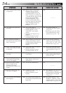
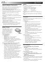
Indicators
y Tally Lamp........................................... ੬ pg. 12
u Power Lamp ........................................ ੬ pg. 12
Other Parts
i Viewfinder ........................................... ੬ pg. 11
o Lens Cover
Opens when the viewfinder is pulled out or the
LCD monitor is opened fully.
p •Remote Sensor .................................. ੬ pg. 40
•Camera Sensor
Be careful not to cover this area, a sensor
necessary for shooting is built-in here.
Q Stereo Microphone .............................. ੬ pg. 50
W Flash ................................................... ੬ pg. 22
E Shoulder Strap Eyelets .......................... ੬ pg. 11
R Battery Pack Mount ............................... ੬ pg. 7
T Grip Strap............................................ ੬ pg. 10
Y LCD Monitor ....................................... ੬ pg. 12
U Speaker ............................................... ੬ pg. 31
I Stud Hole ............................................ ੬ pg. 11
O Tripod Mounting Socket ....................... ੬ pg. 11