E18
VIDEO OUTPUT
TO CAMERAS(Y/C) OUTPUT
DC 12V=OUTPUT
EITHER
OUTPUT
MAX 1.25A
SEE INST-
RUCTION
MANUAL
AA-P700
AC
SEE INSTRUCTION MANUAL
POWER
DC IN
REMOTE
MONITOR
LENS
FREEZE
PLAY
SETDOWN
AW/SELSEND
SCSI
UPMENU
MODE
REC
ON 1 2 3 4
Connecting power
2. Before recording (continued)
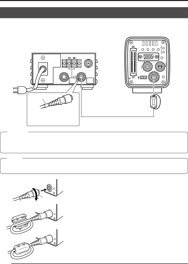
Between the 8 pin DC IN terminal on the rear of the main unit and the 8 pin TO CAMERA
terminal of the AC adapter (AA-P700) connect the power cable (2m) which is provided.
ⅥAfter inserting the plug completely, tighten the secur-
ing ring. (Figure 1)
Make sure white indication of power cable comes to
AA-P700 side.
ⅥTo minimise emission of unwanted electrical waves,
mount certainly the provided clamp filter as shown in
Figure 2 and 3 on the left.
Wind the power cable once around the clamp filter.
ⅥEnsure that the clamp filter is mounted as close to
the camera as possible as shown in the diagram.
D
C
IN
PO
W
ER
D
C
IN
PO
W
ER
DC IN
PO
W
ER
AC adapter
Provided power cable
Provided
Clamp filter
Plug
Ring
Figure 1
Figure 2
Figure 3
Connect the end with the
white marking to the AC
adapter.
White marking
MEMO
• Wait at least 10 seconds before turning the power switch back on, when it has just been turned off.
• Turning the power switch on and off quickly may cause malfunctions, such as failure to boot, etc.
CAUTION
• Be sure to use the AA-P700 power supply.
• Before connecting power cable, make sure that the power switch on the AA-P700 is set to OFF.
Connecting with the power switch on may result in camera malfunction.


