


100
Chapter 8 Menu Description Tables (continued)
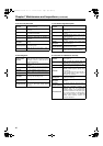
8-2-3 REC FUNCTION 8-2-4 OUTPUT SEL
The ____ in the Adjustable Range column indicates the
preset mode.
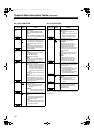
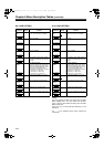
Items/
Data Saved
Adjustable
Range
Remarks
PRE REC
MODE
ON
OFF
Select whether or not to enable PRE
RECORDING.
ON: PRE RECORDING enabled.
OFF: PRE RECORDING disabled.
<Note>
Specify the PRE RECORDING time by
using the menu option PRE REC TIME.
–CUF–
PRE REC TIME 1SEC
:
8SEC
:
15SEC
Set PRE RECORDING.
1-15SEC:
Set the length of time that can be
retrospectively recorded before the
REC START button is pressed.
<Note>
The maximum selectable range is 8
seconds when the REC MODE in the
<SYSTEM MODE> screen is set to
50M (DVCPRO50).
–CUF–
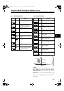
LOOP REC
MODE
ON
OFF
Select whether or not to enable LOOP
REC.
This setting can be used with PRE
RECORDING features.
ON: Enable LOOP REC.
OFF:Disable LOOP REC.
<Note>
After the power is turned off, this item
will default to OFF the next time the
power is turned on.
–––F–
VOICE MEMO
RESERV
ON
OFF
Set the available memory space for
voice memos in P2 cards.
ON: Reserve a voice memo area of 10
minutes or longer separately from
the video recording capacity. The
voice memo area can be used
even when FULL is displayed for
the recording capacity of the P2
card.
OFF:Do not reserve any voice memo
space.
<Note>
Even when this item is set to OFF, and
FULL is displayed for the P2 card’s
recording capacity, it may be possible to
record voice memos depending on the
status of the P2 card.
–CUF–
REC START ALL
NORMAL
Select operating modes that allow
recording to start.
ALL: Allow recording to start during
stop, recording pause, and
playback.
NORMAL:
Allow recording to start during
stop and recording pause.
–CUF–
P.ON REC
SLOT SEL
HOLD
SLOT1
Select the recording order of the slot
when the power is turned on.
HOLD:
The recording order starts with the
card previously selected when the
power was turned off.
SLOT1:
The recording order starts with the
card that is inserted in Slot 1 when
the power is turned on.
–CUF–
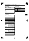
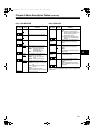
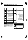
Items/
Data Saved
Adjustable
Range
Remarks
VIDEO OUT
SEL
VBS
VF
Y
Select the output signal on the VIDEO
OUT connecter.
VBS:Output a regular composite
signal.
VF: Output a VF Y signal. The status
display is also superimposed.
Y: Output a component Y signal.
–CUF–
OUTPUT CHAR MENU
ONLY
TC
STATUS
Set the character contents
superimposed onto the output signals
for the VIDEO OUT connecter.
MENU ONLY:
Displays only when the menu
characters are superimposed. No
display appears when other
characters are superimposed.
TC:Display the time code. (Displays the
menu when menu characters are
superimposed.)
<Note>
The TC display position moves up and
down depending on the camera ID
position.
STATUS:
Display the same characters
superimposed on the VF signal.
(Displays the menu when menu
characters are superimposed.)
–CUF–
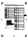
LCD MON
CHAR
ON
OFF
Select whether or not to superimpose
characters on the LCD monitor. (The
character content is the same as the
video output signal.)
ON: Enable superimpose.
(Not interlocked with the VIDEO
OUT CHARACTER switch.)
OFF:Disable superimpose.
(Not interlocked with the VIDEO
OUT CHARACTER switch.)
–CUF–
VF MODE EE/PB
EE
Select the image to display in the
viewfinder.
EE/PB
: Display the playback image in
the playback mode.
EE: Always display the camera
image.
–CUF–
THUMBNAIL
OUT
ON
OFF
Select whether or not to output clip
thumbnails displayed on the LCD
monitor to the video output signals.
ON: Enable output.
OFF:Disable output.
–CUF–
#,52%2'PINKUJDQQMࡍࠫ㧞㧜㧜㧡ᐕ㧝㧞㧤ᣣޓᧁᦐᣣޓඦᓟ㧝㧞ᤨ㧠㧥ಽ