


12
Locations and Functions of Parts
Chapter 1 Overview
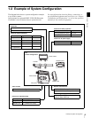
The necessary settings are made using the NETWORK
menu displayed on the viewfinder or monitor screen.
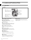
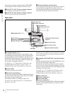
i DC OUT 12V (DC 12V power output) connector
DC 12V power can be fed to an accessory.
j DC OUT 24V (DC 24V power output) connector
DC 24 V power can be fed to an accessory.
k Measure hook/focus reference mark
Use as reference for focusing. The same reference mark is
also provided at the right of the riser plate (page 13).
For actual measurement of the distance from a subject, you
can fix the end of a tape measure to the hook.
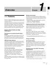
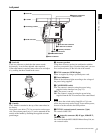
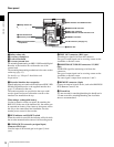
Right panel
a Assignable buttons 1, 2, 3
You can assign various functions to these buttons, using
the subdisplay on the left panel or on the assistant panel or
the menu displayed on the viewfinder or monitor screen.
The ND filter selection function is assigned to button 1 and
the CC filter selection function to button 2 at the factory.
(No function is assigned to button 3.)
For details, see “3-2-10 Allocation of Functions to the
Assignable Buttons and Switch” (page 33) and “3-7
Detailed Settings of the Switch Functions” (page 44).
b LOCK switch
To disable operations on the panel.
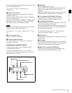
c RUN button and indicator
To start/stop recording on the SRW-1 HD Portable Digital
Recorder docked on the camera. The indicator is lit while
the recorder is in Recording mode.
The indicator flashes as a warning in some cases.
For details on warning indication, see “Warning/Error
Messages” (page 91).
The firmware of the SRW-1 may be required to be updated
for use with this camera. For details, consult your local
Sony representative.
d Assignable 4/AUTO BLK BAL (auto black balance)
switch
Push the switch downward to the AUTO BLK BAL side to
start the auto black balance adjustment.
The function activated by pressing the switch upward to
the 4 side can be selected using the subdisplay on the left
panel or on the assistant panel or the menu displayed on the
viewfinder or monitor screen.
For details, see “3-2-10 Allocation of Functions to the
Assignable Buttons and Switch” (page 33) and “3-7
Detailed Settings of the Switch Functions” (page 44).
e Safety release tab
f Accessory clamp lever
g Lock release knob
h Accessory mount lever
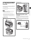
For mounting/unmounting an SRW-1 HD Portable Digital
Recorder or the supplied interface box to the top of the
camera head.
123
LOCK
VF MENU/DISPLAY CANCEL/STATUS
4
AUTO
BLK
BAL
PAG E
RUN
SET
CLEAR
FILTER
ND
1
1/4 ND
2
1/16ND
3
1/64ND
4
CAP
5
5600K
CC
A
3200K
B
4300K
C
6300K
D
1/2 ND
E
1
1
PRO
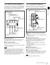
b LOCK switch
cRUN button and indicator
d 4/AUTO BLK BAL switch
iMemory stick section
fAccessory clamp lever
g Lock release knob
a Assignable buttons 1, 2, 3
jFocus reference mark
kTripod receptacles (bottom)
eSafety release tab
h Accessory mount lever
Display/menu operation block
(page 13)
Riser plate