


32
Basic Settings with the Subdisplay
Chapter 3 Basic Adjustments and Settings
3-2-7 Confirmation of the Time Code
and Tape Remaining
When the SRW-1 HD Portable Digital Recorder is attached
to this camera, the time code of the recorder and
approximate tape remaining (unit: minutes) can be
confirmed on the subdisplay.
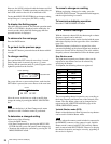
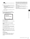
Time code/tape remaining display page
The time code is displayed on the first line, and the
approximate tape remaining is displayed on the second
line, in the range of 1 to 99 min.
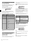
Time code that is displayed on the first line
The type of the displayed time code data is linked with the
SRW-1. Select the type of the displayed time code data on
the SRW-1.
3-2-8 Confirmation of the Power
Voltage and Selection of Fan
Operation Mode
The values in voltage of the power sources connected to
the camera can be confirmed on the subdisplay.
On the same page, the operation mode of the built-in fans
can also be selected.
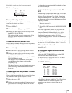
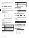
Voltage confirmation/Fan Operation mode select
page
At
1 and 2 on the first line, the values in voltage of the
12-V and 24-V power systems are displayed, respectively.
If power is not supplied, “- -” is displayed.
If the voltage falls to the NEAR END level, the indication
starts flashing. If the voltage falls further down to the END
level, the indication flashes rapidly.
The NEAR END and END levels can be set on the <BATT
ALARM SET> page of the MAINTENANCE menu.
On the second line, Fan Operation mode can be changed.
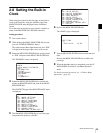
3-2-9 ON/OFF of the Character
Indication
Superimposition of character data onto camera images can
be activated or deactivated by output destination.
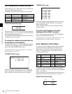
Character indication setting page
VF1
Viewfinder connected via the VF1 connector (default: ON)
MON
Monitors connected via the MONITOR OUT HD SDI
connectors (default: ON)
VBS
Monitors connected via the TEST OUT and REMOTE
connectors (default: ON)
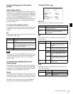
Indication Meaning
TCR 00:00:00:00 Time code data of the LTC reader
TCR 00:00.00:00 Time code data of the LTC reader (DF)
TCR.00:00:00:00 Time code data of the VITC reader
UBR 00 00 00 00 User bit data of the LTC reader
UBR.00 00 00 00 User bit data of the VITC reader
TCG 00:00:00:00 Time code data of the time code
generator
TCG 00:00:00.00 Time code data of the time code
generator (DF)
UBG 00 00 00 00 User bit data of the time code
generator
CTL -0:00:00:00 Data of the CTL counter
T*R 00:00:00:00 Time code cannot be read with the
LTC reader
U*R 00 00 00 00 User bit cannot be read with the LTC
reader
T*R.00:00:00:00 Time code cannot be read with the
VITC reader
U*R.00 00 00 00 User bit cannot be read with the VITC
reader
TCR 00:00:00:00
20min
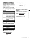
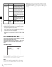
Setting Operation of the fans
AUTO1 (default) The fans rotate at the standard speed.
AUTO2 The fans rotate at the minimum speed
equivalent to the MIN speed in REC
mode. In other conditions, the fans
rotate at the speed equivalent to the
AUTO1 speed.
MIN The fans rotate at the minimum speed.
MAX The fans rotate at the maximum speed.
11.4V 24.1V
FAN:AUTO1
12
VF1:ON
MON:ON VBS:ON