


10
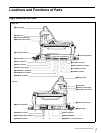
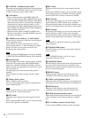
Locations and Functions of Parts
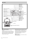
a Up tally lamp
Lights when the camera receives a red tally signal.
When the CALL button on the MSU-900/950 Master
Setup Unit or the RCP-700/900-series Remote Control
Panel is pressed, the lamp lights if previously off or goes
off if previously on. The brightness of the lamp can be
adjusted by menu operation. Setting the UP TALLY switch
on the rear panel to OFF will keep the lamp from lighting.
To display the camera number, attach a supplied number
plate (0 to 9) or select the desired number on the menu.
b Safety lock
Locks the side panel to prevent accidental opening. To
open the side panel, loosen the side panel lock screws,
slide the safety lock towards the lens, and open the panel.
The side panel locks automatically when closed.
c Camera number plate
Attach a light gray number plate (supplied) to display the
camera number.
d Side panel lock screws
These screws secure the side panel. Turn clockwise until
tight to lock the panel.
e Lens lock and knob
These lock the lens. To attach or remove a lens, turn the
knob counterclockwise until the lens lock is horizontal. To
secure the lens, turn the knob clockwise until the lens lock
is vertical.
To attach a large lens, remove the pin from the bayonet
mount of the lens.
f Cable clamp
To secure the fiber optic cable.
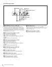
g Accessory bracket
To secure optional accessories such as the BKP-7911
Script Holder.
For more information on attaching an accessory, see the
accessory’s operation manual.
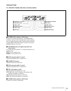
h SDI 1 connector (BNC type)
To output the HD-SDI signals.
For details on the output signals, see “Setting the Camera
Outputs” (page 22).
i SDI 2 connector (BNC type)
To output the HD-SDI or SD-SDI signals.
For details on the output signals, see “Setting the Camera
Outputs” (page 22).
j TEST OUT (test signal output) connector (BNC
type)
To output the analog signal.
This also supplies the VBS signal, an HD signal nearly
equal to the signal output from the VF connector, an HD-
SYNC signal, or an SD-SYNC signal depending on which
of these you have selected on the menu.
For details on the output signals, see “Setting the Camera
Outputs” (page 22).
k PROMPTER 1 connector (BNC type)
To output the signal input from the camera control unit’s
PROMPTER INPUT connector. If the connected camera
control unit has two prompter inputs, a signal of prompter
1 is output.
l PROMPTER 2 connector (BNC type)
To output the signal input from the camera control unit’s
PROMPTER 2 INPUT connector. This is enabled only for
the unit which has the PROMPTER 2 input.
m REMOTE connector (8-pin)
To connect the camera to an optional MSU-900/950
Master Setup Unit, or RCP-700/900-series Remote
Control Panel, or RM-series Remote Control Unit via a
CCA cable. The connected unit may then control the
camera.
When the camera is connected to a CCU, do not connect
any device to this connector.
n CRANE connector (12-pin)
For interface with a viewfinder or external data.
o TRACKER connector (10-pin)
For communication between the camera operator and the
tracker, and also for intercom channels 1 and 2. It also
supplies the up tally signal and the program audio signal.
p RET (return video) CONTROL connector (6-pin)
To connect a CAC-6 Return Video Selector.
q DC OUT connector (4-pin)
To supply power to a script light of the BKP-7911 Script
Holder.
r AUDIO IN 1 switch
Set this switch according to the device connected to the
AUDIO IN 1 connector.
MIC: When connecting a microphone
LINE: When connecting the signal of line level (0 dBu)
s Microphone power switches
For the microphones connected to the AUDIO IN 1 and 2
connectors, respectively.
Note
Note