


15
Locations and Functions of Parts
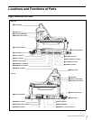
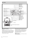
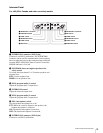
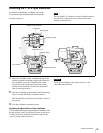
Intercom Panel
For JN3 (USA, Canada, and other countries) models
a INTERCOM 1 connector (XLR 5-pin)
Connects to an XLR 5-pin headset. The INTERCOM 1
connector can be used for communication via the engineer
line even when the power to the camera has been turned off
from the HDCU1000/1500 Camera Control Unit and the
POWER indicator is lit in red.
b ENG/PROD (intercom engineer/producer line
select) switch
To switch intercom channel 1 or 2 between producer and
engineer lines.
ENG: Use the engineer line.
PROD: Use the producer line.
c PGM (program audio) 1 control
Adjust the program audio 1 output level.
d INTERCOM control
Adjust the intercom output level.
e PGM (program audio) 2 control
Adjust the program audio 2 output level.
f MIC (microphone) switch
Turn the headset microphone on or off.
PTT: While the switch is flipped to this position, the
headset microphone is turned on.
ON: The headset microphone is turned on.
OFF: The headset microphone is turned off.
g INTERCOM 2 connector (XLR 5-pin)
Connects to an XLR 5-pin headset.
ENG PROD
INTERCOM
PTT ONOFF
PGM1
MIC
INTERCOM 1 INTERCOM 2
PGM2
ENG PROD
INTERCOM
PTT ONOFF
PGM1
MIC
PGM2
aINTERCOM 1 connector
bENG/PROD switch
cPGM1 control
dINTERCOM control
ePGM2 control
fMIC switch
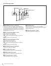
b ENG/PROD switch
c PGM1 control
d INTERCOM control
e PGM2 control
f MIC switch
g INTERCOM 2 connector