


14
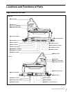
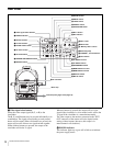
Locations and Functions of Parts
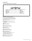
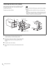
p VF DETAIL (viewfinder detail) control
Adjust the amount of detail of the picture on the viewfinder
screen when the VF DETAIL switch is set to ON. This has
no effect on the output signal of the camera.
q CALL button
• Press to call the operator of the HDCU1000/1500
Camera Control Unit, the MSU-900/950 Master Setup
Unit, or the RCP-700/900-series Remote Control Panel.
When pressed, the camera’s red tally lamp will light up
if previously off, and turn off if previously on. The
CALL button on the MSU-900/950 Master Setup Unit or
RCP-700/900-series Remote Control Panel will light up,
and their buzzer will sound.
• When the CALL button on the RCP-700/900-series
Remote Control Panel or the MSU-900/950 is pressed,
this button will light up.
r CURSOR (cursor memory) 1, 2, and 3 buttons
To store the size and position of the box cursor displayed
on the viewfinder screen.
Three different box cursor settings may be stored in
memory using buttons 1, 2, and 3. Pressing one of these
buttons will cause a cursor of the stored size to be
displayed in the stored position.
When one of the CURSOR buttons is lit up, the H-POSI,
V-POSI, WIDTH, and HEIGHT buttons will be disabled.
s Back tally lamp
This lamp lights red when the red tally signal is supplied.
When the CALL button on the MSU-900/950 Master
Setup Unit or the RCP-700/900-series Remote Control
Panel is pressed, the lamp lights if previously off or goes
off if previously on.
The lamp lights green when the green tally siganl is
supplied.
You can display the camera number selected with the
menu.
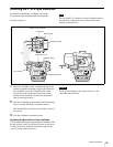
t “Memory Stick” section
Insert a “Memory Stick” to the slot.
The access lamp lights while writing or reading data to/
from a “Memory Stick.”
When the access lamp is lit, do not insert/remove the
“Memory Stick” or turn off the camera.
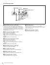
u RET 2 knob
This knob selects from the four return signals from the
CCU.
By pressing in the RET 2 button, you can view the selected
return video signal in the viewfinder.
v RET 1 knob
This knob selects from the four return signals from the
CCU.
By pressing in the RET 1 button, you can view the selected
return video signal in the viewfinder. The signal supplied
from the TEST OUT connector will also be switched.
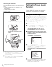
w RET 2 button
By pressing in this button, you can view the return video
signal selected by the RET 2 knob, in the viewfinder.
Pressing this button again will switch the viewfinder and
monitor screen display back to the camera’s video signal.
x RET 1 button
By pressing in this button, you can view the return video
signal selected by the RET 1 knob, in the viewfinder.
Pressing this button again will switch the viewfinder and
monitor screen display back to the camera’s video signal.
If both the RET 1 and RET 2 buttons are pressed, RET 1
will be displayed.
y CURSOR STORE button
Press this button to store the size and position of the box
cursor in memory.
If the CURSOR ON button is not lit, box cursor
information will not be stored.
z CURSOR ON button
When this button is pressed, the button will light up and the
box cursor will be displayed on the viewfinder screen.
When the button is pressed again, the light will go off and
the box cursor will disappear.
wj HEIGHT control
Adjust the height of the box cursor displayed on the
viewfinder screen within the effective resolution area.
wk V-POSI (vertical position) control
Adjust the vertical position of the box cursor displayed on
the viewfinder screen within the effective resolution area.
wl WIDTH control
Adjust the width of the box cursor displayed on the
viewfinder screen within the effective resolution area.
e; H-POSI (horizontal position) control
Adjust the horizontal position of the box cursor displayed
on the viewfinder screen within the effective resolution
area.
ea VF (viewfinder) connector (D-sub 25-pin)
Connect to the CAMERA connector on the viewfinder.
Note
Note
Note
Note