


25
Menu Operations
When you set the MENU SELECT switch to
CANCEL
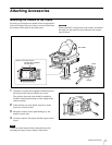
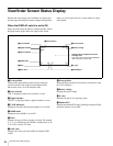
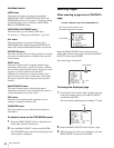
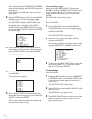
The status display is changed to show the following items:
a Assignable switch indication
The function assigned to the assignable switch (page 13) is
inidcated.
For the functions that can be assigned, see OPERATION
menu <SWITCH ASSIGN1> (page 35).
b Format indication
The current video format is displayed.
c ‘!’ indication area
This area can be used to display abnormal statuses using
the <‘!’ IND> function.
For details, see OPERATION menu <‘!’ IND> (page 33).
d Light-receiving level indications
This area shows the light-receiving levels in segments.
CHU: Light-receiving level at the CCU connector (page
11) of the camera
CCU: Light-receiving level at the CAMERA connector of
the CCU
If a camera control unit other than an HDCU1000/1500 is
connected, correct indications may not be obtained.
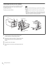
Menu Operations
The menus displayed on the viewfinder enable various
settings of the camera.
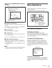
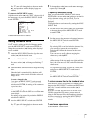
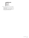
The following parts are used to operate the menus.
Starting Menu Operations
To display a menu page
Move the DISPLAY switch from OFF to MENU.
The menu page that last operated will be displayed. (If it
is the first time, the CONTENTS page of the OPERATION
menu will be displayed.)
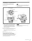
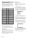
To display the TOP MENU screen
While pressing the MENU SELECT switch toward
ENTER, set the DISPLAY switch from OFF to MENU,
and “TOP” is displayed at the upper right corner of the
screen. Selecting it displays the TOP MENU screen, which
lists the available menus, and you can select the menus on
this screen.
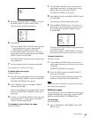
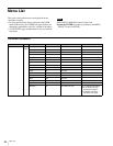
TOP MENU screen
To disable the “TOP” indication
Turn the power once off then on again, or set the DISPLAY
switch from OFF to MENU while pressing the MENU
SELECT switch toward CANCEL. This disables the TOP
selection.
Note
FORMAT :1080-59.94i
ASSIGNABLE :OFF
!ND :
!CC :
!FAN :MAX
!EXT :ON
!FORMAT :1080-60i
OPT LV CHU:
X
X
X
X
X
S
S
S
g
CCU:
X
X
X
X
X
S
S
S
g
a Assignable switch indication
c ‘!’ indication area
dLight-receiving level indications
bFormat indication
1
POWER
R G B RET 2
FILTER LOCAL
ND
2
3
4
1
5
2
3
4
1
2
3
4
1
CC
B
C
D
A
E
H-POSI V-POSI
WIDTH HEIGHT STORE
CURSOR
VF DETAIL
123
ON
UP TALLY
ON
OFF
16:9
4:3
VF
SCAN
ON
OFF
SCREEN SIZE
MARKER
ON
OFF
MARKER
ON
OFF
ON
OFF
MIX VF
ON
MENU
DISPLAY
OFF
MENU SELECT
CANCEL ENTER
CALL
RET 1
ASSIGN-
ABLE
MENU SELECT knob
MENU SELECT switch
DISPLAY switch
<TOP MENU>
USER
USER MENU CUSTOMIZE
ALL
OPERATION
PAINT
MAINTENANCE
FILE
DIAGNOSIS