


12
Locations and Functions of Parts
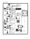
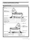
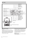
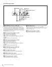
Rear Panel
a Video signal select buttons
Select the video output signal (R, G, or B) to the
viewfinder.
The R, G, and B buttons may be pressed individually or in
combination. The signal corresponding to each pressed
button will be output. When two buttons are pressed, the
output will consist of those two signals mixed together.
When all three buttons are pressed, the output to the
viewfinder will be the Y signal.
When no buttons is pressed, the output will be a color
signal if the viewfinder is a color model, and it will be the
Y signal if the viewfinder is a monochrome model.
The video output to the monitor connected to the TEST
OUT connector of the camera will also depend on the
setting of these buttons (however, this output is in
monochrome in all situations).
b POWER indicator
This indicator lights up or goes off as follows to indicate
the power supply status:
1
1
POWER
R G B RET 2
FILTER LOCAL
ND
2
3
4
1
5
2
3
4
1
2
3
4
1
CC
B
C
D
A
E
H-POSI V-POSI
WIDTH HEIGHT STORE
CURSOR
VF DETAIL
123
ON
UP TALLY
ON
OFF
16:9
4:3
VF
SCAN
ON
OFF
SCREEN SIZE
MARKER
ON
OFF
MARKER
ON
OFF
ON
OFF
MIX VF
ON
MENU
DISPLAY
OFF
MENU SELECT
CANCEL ENTER
CALL
RET 1
aVideo signal select buttons
bPOWER indicator
dCC filter selector
eFILTER LOCAL button
fUP TALLY switch
gVF SCAN switch
hSCREEN SIZE MARKER switch
iMARKER switch
j MIX VF switch
k DISPLAY switch
l MENU SELECT switch
cND filter selector
m MENU SELECT control
n ASSIGNABLE switch
p VF DETAIL control
qCALL button
rCURSOR 1, 2, and 3 buttons
sBack tally lamp
t“Memory Stick” section
uRET 2 knob
vRET 1 knob
w RET 2 button
x RET 1 button
o VF DETAIL switch
y CURSOR STORE button
z CURSOR ON button
wkV-POSI control
wlWIDTH control
e; H-POSI control
ea VF connector
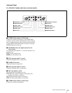
Memo clip
Intercom panel (page 15 and page 16)
wj HEIGHT control