


22
Setting the Camera Outputs
value. Use this setting when an optimum sensitivity value cannot be
obtained, depending on the shooting environment.
2) Normally, the optimum offset is automatically set in conjunction with
the AREA MARKER SIZE and MASTER GAIN set values. Use this
setting when the optimum offset cannot be obtained, depending on
the shooting environment.
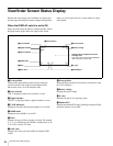
To use the area marker
Setting AREA MARKER to ON displays the detection
area of the focus as a marker on the viewfinder screen.
You can set the size and position of the detection area
with the menu items below.
SIZE: The size of the detection area can be changed.
(If the area size is too large, both the subject and the
background are included in the area, making the
indicator display may easily deviate from the
subject.)
POSITION: Roughly set the position of the detection
area.
POSITION H: Finely adjust the position of the
detection area in the horizontal directions.
POSITION V: Finely adjust the position of the
detection area in the vertical directions.
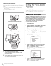
4
Rotate the MENU SELECT knob to display the
desired setting, then press the MENU SELECT switch
toward ENTER.
5
To finish the adjustment, set the DISPLAY switch to
OFF to exit Menu mode.
• The level indicator and the effect area marker cannot be
displayed simultaneously, whichever you set to ON later
is preferentially displayed.
• The area marker and the aspect safety marker cannot be
displayed simultaneously, whichever you set to ON later
is preferentially displayed.
• When displaying the focus assist indicators, check that
the flange focal length has been precisely adjusted.
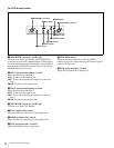
Setting the Camera
Outputs
You can specify video signals directly output from the
camera with menu operations.
The MAIN (camera picture), RET (return signal), or VF
(the same picture as that displayed on the viewfinder)
setting is common to SD-SDI and VBS. Different signals
cannot be output.
The menu pages used for the output settings have been
registered to the USER menu at the factory.
• <POWER SAVE>
• <OUTPUT FORMAT>
• <TEST OUT>
• <SDI-2 OUT>
• <DOWN CONVERTER>
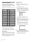
Set the following menu items to the settings shown in the
table.
For details on menu operations and the USER menu, see
“Menu Operations” on page 25.
Outputting the signal being shot by the
camera
The same textual information as those displayed on the
viewfinder can be added to the output signal by setting
CHARACTER to “ON” on the <SDI-2 OUT> or <TEST
OUT> page.
To output as HD-SDI
To output as SD-SDI
Notes
Note
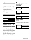
Menu page Item Setting
<POWER SAVE> SDI-2 OUT ACTIVE
<SDI-2 OUT> OUTPUT MAIN
Menu page Item Setting
<POWER SAVE> SDI-2 OUT ACTIVE
DOWN CONVERTER ACTIVE
<DOWN CONVERTER> OUTPUT SIGNAL MAIN
<SDI-2 OUT> OUTPUT SD-SDI