


6
Overview
Versatile detail control functions
Skin-tone detail function
This function allows control (emphasis or suppression) of
the detail level for just a certain hue or chroma area in the
image, by creating a detail gate signal from color
components of your specified hue, such as skin tones.
The detail levels of three hues can be adjusted
independently at the same time.
Detail boost-frequency control
The boost frequency can be adjusted from 20 to 30 MHz.
This allows the detail thickness to be set appropriately for
the subject, thus enabling more subtle image expression.
H/V ratio control
The ratio between horizontal and vertical detail can be
adjusted.
White/black limiter
The white and black details can be limited independently.
Easy menu-based setting
Selections and settings for viewfinder display items,
safety-zone marker
2)
or center marker,
3)
screen size
marker, etc. can be made quickly and easily, using setup
menus displayed on the viewfinder screen or an external
monitor.
2) Safety zone marker: A box-shaped marker displayed on the viewfinder
screen which indicates 80%, 90%, 92.5%, or 95% of the total screen area.
3) Center marker: A cross-shaped marker which indicates the center of the
viewfinder screen.
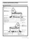
Wide variety of viewfinder display options
Along with items such as operation messages, a zebra
pattern,
4)
a safety-zone marker, and a center marker,
camera settings may also be displayed on the viewfinder
screen. Furthermore, there are other indicators arranged
above and below the viewfinder, such as a tally lamp,
battery warning indicator, and an indicator to tell you that
one or more settings are other than standard. This makes
it simple to check the status of the camera.
4) Zebra pattern: A stripe pattern displayed on the viewfinder screen which
indicates the portions where the video level is above about 70% or 100%.
Used to check the video level of the subject.
Optical digital transmission
The camera uses electro-optical coding cable for 1.5-
gigabit digital optical transmission between the camera
and a Camera Control Unit.
Prevention of electrical shock
When the power connection is unsafe, the power supply
from the connected Camera Control Unit will be shut off.
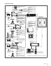
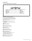
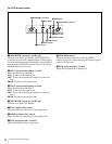
Basic System Configuration
Examples of devices and parts that may be used with the
HDC1000R are shown on the next page.
Production of some of the peripherals and related devices
shown in the figures has been discontinued.
For advice on choosing devices, please contact your Sony
dealer or a Sony sales representative.
Note