


16
Locations and Functions of Parts
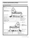
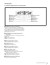
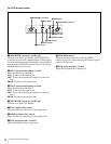
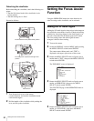
For CED (Europe) model
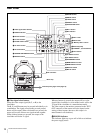
a INTERCOM 1 connector (XLR 5-pin)
Connects to an XLR 5-pin headset. The INTERCOM 1
connector can be used for communication via the engineer
line even when the power to the camera has been turned off
from the HDCU1000/1500 Camera Control Unit and the
POWER indicator is lit in red.
b MIC1 (intercom microphone 1) switch
Select the talk line for intercom 1.
ENG: To talk over the engineer line
OFF: To turn off the headset microphone for intercom
line 1
PROD: To talk over the producer line
c MIC2 (intercom microphone 2) switch
Select the talk line for intercom 2.
ENG: To talk over the engineer line
OFF: To turn off the headset microphone for intercom
line 2
PROD: To talk over the producer line
d INTERCOM 2 connector (XLR 5-pin)
Connects to an XLR 5-pin headset.
e ENG (engineer line) control
Adjust the intercom audio level of the engineer line.
f PROD (producer line) control
Adjust the intercom audio level of the producer line.
g PGM (program audio) 1 control
Adjust the program audio 1 output level.
h TRACKER control
Adjust the intercom audio level at the TRACKER
connector (page 10) on the connector panel when using the
connector for intercom.
i PGM (program audio) 2 control
Adjust the program audio 2 output level.
ENG
INTERCOM 1 INTERCOM 2
PROD PGM1
MIC2TRACKER
ENG PRODOFF ENG PRODOFF
MIC1
PGM2
gPGM1 control
h TRACKER control
iPGM2 control
a INTERCOM 1 connector
b MIC1 switch
cMIC2 switch
e ENG control
dINTERCOM 2 connector
f PROD control