


13
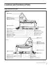
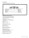
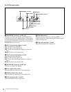
Locations and Functions of Parts
Green: Power is being supplied to the camera.
Red: Power is being supplied to the camera, but the CAM
PW button of the MSU-900/950 Master Setup Unit or
RCP-700/900-series Remote Control Panel is set to
OFF.
Yellow: Power is being supplied to the camera, but the VF
PW button of the MSU-900/950 Master Setup Unit or
RCP-700/900-series Remote Control Panel is set to
OFF, and power is not being supplied to the viewfinder.
Off: Power is not being supplied to the camera.
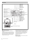
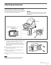
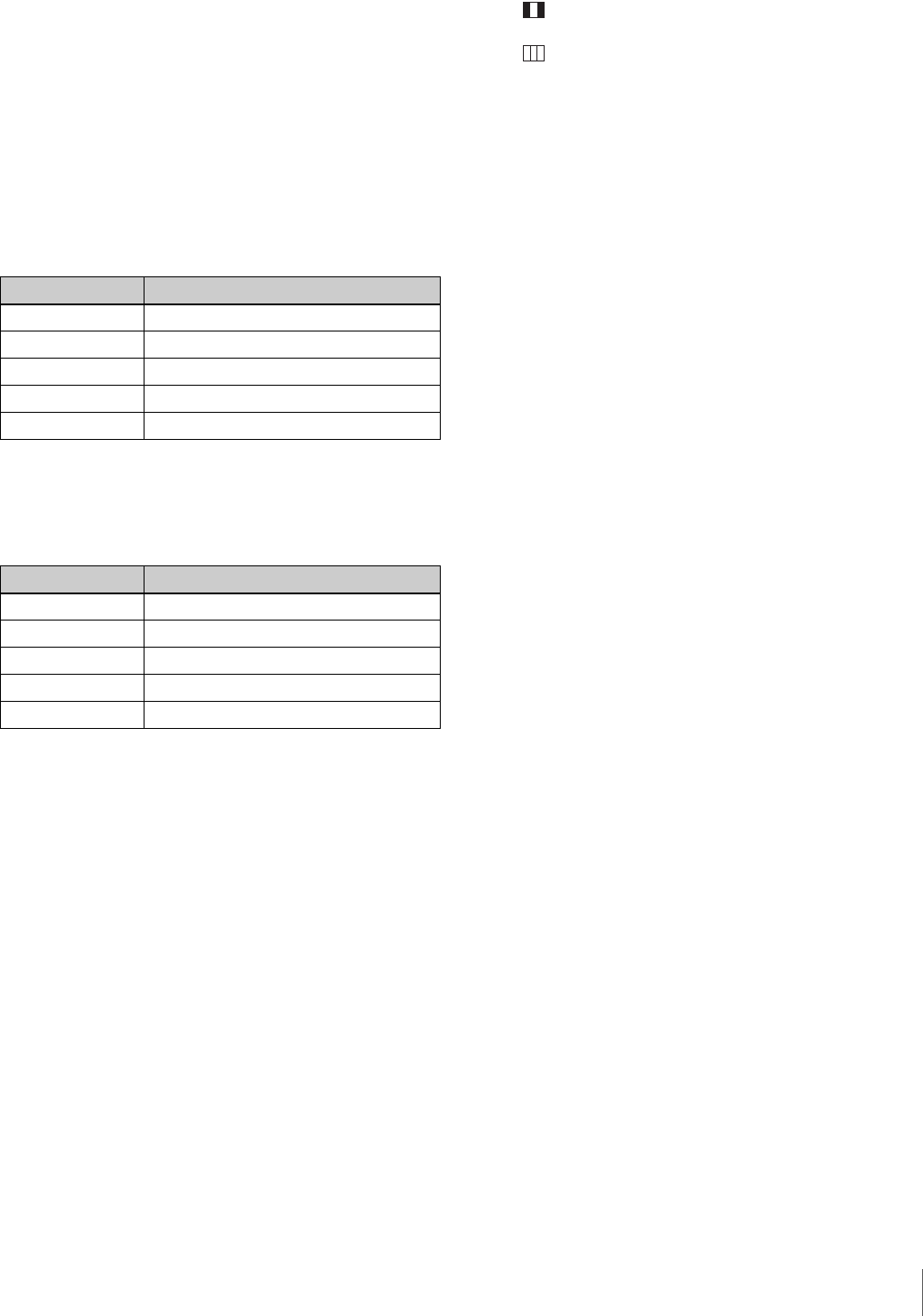
c ND filter selector
When the FILTER LOCAL button is lit up, this selector
may be used to select an ND filter.
d CC (color temperature conversion) filter selector
When the FILTER LOCAL button is lit up, this selector
may be used to select a color temperature conversion filter
appropriate to the light source illuminating the subject.
e FILTER LOCAL (filter local control) button
Pressing this button enables selecting of a color
temperature conversion filter using the CC filter selector or
an ND filter using the ND filter selector. Pressing the
button again gives control of the filters to the MSU-900/
950 Master Setup Unit or RCP-700/900-series Remote
Control Panel.
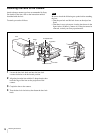
f UP TALLY switch
Set whether or not the camera’s Up Tally lamp and the
lens’ tally lamp will light when the camera receives a red
tally signal.
ON: The tally lamps will light.
OFF: The tally lamps will not light.
g VF (viewfinder) SCAN switch
To control the viewfinder screen display.
16:9: To set the viewfinder display to 16:9 aspect ratio.
4:3: To set the viewfinder display to 4:3 aspect ratio.
h SCREEN SIZE MARKER switch
To control the display of the screen size marker as follows:
ON ( ): Areas outside the specified ratio area will be
darkened.
ON ( ): The screen size marker (white lines) will be
displayed.
OFF: The screen size marker will not be displayed.
i MARKER switch
To control the display of the marker as follows:
ON: A marker selected from the menu will be displayed on
the viewfinder screen.
OFF: The marker will not be displayed.
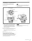
j MIX VF (mix viewfinder) switch
You can see the mixed signal of the camera’s output signal
and the return video signal on the viewfinder screen.
ON: This function is enabled. You can see the mixed signal
of the camera’s output signal and the selected return
video signal (return video 1 or 2) on the viewfinder
screen when you press the RET 1 or RET 2 button.
OFF: This function is disabled.
k DISPLAY switch
The functions of the DISPLAY switch are as follows:
ON: Text and messages describing the camera settings and
operating status may be displayed on the viewfinder
screen.
OFF: Status messages will not appear on the viewfinder
screen.
MENU: Menus for camera settings will be displayed on
the viewfinder screen.
l MENU SELECT switch
The functions of the MENU SELECT switch are as
follows:
ENTER: Confirm the menu or page selected using the
MENU SELECT control, or confirm setting values.
CANCEL: Cancel menu setting values or return to the
previous menu.
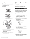
m MENU SELECT control
To select menu items or change setting values in the menus
displayed on the viewfinder screen.
n ASSIGNABLE switch
You can assign a function, such as lens extender ON/OFF,
using the menu.
o VF DETAIL (viewfinder detail adjustment) switch
ON: Emphasizes the contours of the image on the
viewfinder screen. When the switch is set to this
position, you can adjust the amount of detail using the
VF DETAIL control.
OFF: Disables contour emphasis.
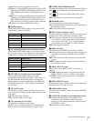
Selector position Selected filter
1 Clear
21/4ND
31/8ND
41/16ND
51/64ND
Selector position Selected filter
A Cross filter
B 3200K (clear)
C 4300K
D 6300K
E 8000K