


2-4: Part I
Teledyne Analytical Instruments
1 Introduction Model 5000B
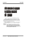
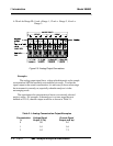
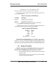
4–20 mA dc Range ID: 8 mA = Range 1, 12 mA = Range 2, 16 mA =
Range 3.
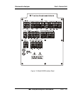
Figure 2-5: Analog Output Connections
Examples:
The analog output signal has a voltage which depends on the sample
concentration AND the currently activated analysis range. To relate the
signal output to the actual concentration, it is necessary to know what range
the instrument is currently on, especially when the analyzer is in the
autoranging mode.
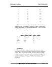
The signaloutput for concentration is linear over currently selected
analysis range. For example, if the analyzer is set on a range that was
defined as 0-10 %, then the output would be as shown in Table 2-1.
Table 2-1: Analog Concentration Output-Examples
Concentration Voltage Signal Current Signal
% Output (V dc) Output (mA dc)
0 0.0 4.0
1 0.1 5.6
2 0.2 7.2