


3 Operation/Control Unit Model 5000B
3-4 Part I
Teledyne Analytical Instruments
the appropriate point in the procedure, in a Monospaced type style. Push-button
names are printed in Oblique type.
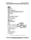
3.3 The System Function
The subfuctions of the System function are described below. Specific
procedures for their use follow the descriptions:
• Dig_Filt: Adjust how much digital filtering should be on the
signal
• SELF-TEST: Performs a self-diagnostic test to check the
integrity of the power supplies, outputs, detector signal and
preamplifier.
• PWD: Login security system for accessing to the setup functions.
• LOGOUT: Prevents an unauthorized tampering with analyzer
settings.
• AUTOCAL: Set the automatic calibrated timer schedule for
Zero and Span cycling.
• FILSOL: Select Span/Zero flag (filter) or Span/Zero solenoid
valve for calibration method.
• TRACK: Set the system reading to be held or followed by the
concentration “fluid or filter” during calibration.
• CAL-HOLD-TIMER: Set the timing for calibration holding
and timing for the sample reading after return to analyze mode.
• ALGORITHM: Linearize the output for nonlinear characteristic.
• APPLICATION: Used to define the analysis ranges and
application (fluid used).
• MODEL: Displays model number and software version.
• OUTPUT: 4-20 MA: Adjust 4 and 20 mA output.
• SHOW_NEG: Whether to display negative readings or not;
affects analog output too. No negative readings is the default.
3.3.1 Setting up an AUTO-CAL
When proper automatic valving is connected, the Analyzer can cycle
itself through a sequence of steps that automatically zero and span the instru-
ment.