


4–17
Operations/Analysis Unit 4
Teledyne Analytical Instruments
A Business Unit of Teledyne Electronic Technologies
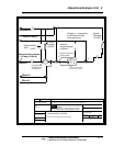
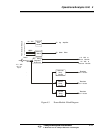
4.4 Operational Theory Cont'd
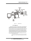
The energy source for the analyzer is most commonly provided by as a
high intensity quartz iodine lamp located in the source module. Quartz iodine
was chosen because it produces sufficient NIR to operate the system and
maintains a nearly constant brightness over its lifetime. (See Figures 2-1 and
2.2).
This energy is then fed through the sample, which is temperature
controlled, and into the detector module where it passes through a rotating
filter wheel before reaching the lead sulfide (PbS) detector (PbSe also used
for longer wavelengths (cooled and non-cooled).
The filter wheel, driven at 30 RPS or 1800 RPM by a synchronous AC
motor, contains two optical filters with bandpasses selected for each applica-
tion, thus providing reference and measuring pulses from which the required
information may be obtained.
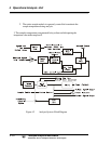
The detector receives pulses at the rate of 60 PPS, or two pulses per
revolution of the filter wheel. Every other pulse is from the measuring filter,
while the alternate pulse is from the reference filter, so that pulses through
the measuring filter alternate with pulses through the reference filter. A filter
position sensor, which is an optical device having an integral light source
and light detector, differentiates between the two.
The two entrained pulses received by the detector each revolution are
amplified through a preamplifier which is physically located inside the sealed
compartment with the filter wheel and detector. This signal is then sent to a
clamping circuit where an exact zero reference is established.
This clamped video signal is then fed through a gain control network,
which is controlled by the automatic gain control loop, through another
amplifier, to the electronic switch. This switch is controlled by the switch
driver network which derives its information from the filter position sensor in
order to separate the entrained video signal into its component parts of a
measuring peak and a reference peak. These peaks are then fed through a
balancing network and channeled into separate peak height detectors which
produce DC voltage levels which are exactly equal to the peak height or
absolute magnitude of the voltage from the base to the peak of each of the
pulses.
At this point the reference signal is fed back to the automatic gain
control loop to maintain the desired system gain. In addition, both the mea-
suring and reference levels are fed to selector switches in order to enable