


4–11
Operations/Analysis Unit 4
Teledyne Analytical Instruments
A Business Unit of Teledyne Electronic Technologies
optical filters. These optical filters are stable and are chosen to indicate the
measured component at the required instrument wavelengths. Therefore,
future, faster, yet much simpler calibration zero and span checks can be
made without the unnecessary tedious on-line calibration described above
nor the consumption of expensive calibration fluids which may be difficult to
handle or obtain, are unstable, or toxic in nature.
A Fitter(s) at the factory is chosen and installed in the instrument (approxi-
mating in absorbance value to the anticipated stream composition back-
ground) to give reproducible zero/ span value when nitrogen or air back-
ground is in the measuring cell. This capability is possible when the zero
offset between the process fluid and dry air or nitrogen remains close to the
zero point of the actual process fluid (i.e., after calibration, the zero off-set
can be adjusted over the entire range of the meter, plus or minus 100 %
from zero). In the case of the calibration zero check value, the requirement
for installing a zero optical flag with dry nitrogen as the background fluid
depends upon how unbalanced the reference and measure channel peak
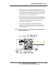
heights are with respect to each other as measured using an oscilloscope at
Test Point 1 (TP1 -Violet)) of the AGC- board designated B-1 4521-4. A
good ratio (ref/meas.) estimate to keep within is (1 volt minimum: 2 volt
maximum) to (2 volt maximum: 1 volt minimum) between the zero process
fluid signal levels and the nitrogen calibration fluid background signal levels.
With the process fluid in the cell at the zero point of the calibration range,
the reference and measure pulses are optically balanced using density
screens placed over the reference and/or measure filters. These signals are
balanced to 9 volts each as measured at TP4 (ref-orange) and TP3 (meas-
yellow) on the PEAK LEVEL DETECTOR BOARD designated B- 14074-
A. The spectral background absorbance at the reference versus measure
wavelengths of the process fluid determines the magnitude of the unbal-
anced ref/meas ratio. This ratio is kept within the 1:2 to 2:1 values for
proper operation of the AGC circuitry and therefore proper stability and
signal/noise levels of the instrument output. After balancing on a zero
sample of the process fluid, if the ratio is not found to be within the 1:2 to 2:1
range, a zero flag is necessary and installed in the sample cell compartment
along with a span flag if ordered. This zero flag when chosen is also
solenoid actuated to bring the ratio within the 1:2 to 2:1 range between
process zero fluid and zero nitrogen or dry air background. The span flag is
actuated while the zero offset level (usually when nitrogen is used as a zero
calibration fluid) is switched in.
Zero calibration check after process on-line calibration.
To check zero on the analyzer, immediately back-flush out the process fluid
and dry the cell out with a reproducible zero fluid that should never contain
any of the analyte. (This is usually done with N2 assuming the process fluid
has low vapor pressure and can be purged dry in an acceptable short time