


2-8: Part I
Teledyne Analytical Instruments
1 Introduction Model 5000B
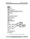
When CRC opens again, zero and span are done, and the sample is
being analyzed.
Note: The Remote Bench terminal strip (section 3.6 Part III) provides
signals to ensure that the zero and span gas valves will be
controlled synchronously.
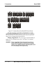
Range ID Relays: Four dedicated RANGE ID CONTACT relays .
The first four ranges are assigned to relays in ascending order—Range 1 is
assigned to RANGE 1 ID, Range 2 is assigned to RANGE 2 ID, Range 3
is assigned to RANGE 3 ID, and Range 4 is assigned to RANGE 4 ID.
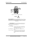
Network I/O: A serial digital input/output for local network protocol.
At this printing, this port is not yet functional. It is to be used in future
versions of the instrument.
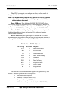
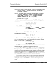
RS-232 Port: The digital signal output is a standard RS-232 serial
communications port used to connect the analyzer to a computer, terminal, or
other digital device. The pinouts are listed in Table 2-3.
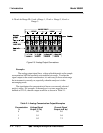
Table 2-3: RS-232 Signals
RS-232 Sig RS-232 Pin Purpose
DCD 1 Data Carrier Detect
RD 2 Received Data
TD 3 Transmitted Data
DTR 4 Data Terminal Ready
COM 5 Common
DSR 6 Data Set Ready
RTS 7 Request to Send
CTS 8 Clear to Send
RI 9 Ring Indicator
The data sent is status information, in digital form, updated every two
seconds. Status is reported in the following order:
• The concentration in percent
• The range is use (HI< MED< LO)
• The span of the range 0-100%, etc.
• Which alarm - if any - are disabled (AL-x DISABLED)