


ii: Part I
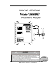
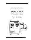
Model 5000B Photometric Analyzer
Teledyne Analytical Instruments
Table of Contents
1 Introduction
1.1 Overview ........................................................................ 1-1
1.2 Typical Applications ....................................................... 1-1
1.3 Main Features of the Analyzer ....................................... 1-5
1.4 Operator Interface .......................................................... 1-6
1.4.1 Up/Down Switch .................................................... 1-6
1.4.2 Escape/Enter Switch.............................................. 1-6
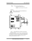
1.5 Control Section Interface Panel...................................... 1-8
2 Installation
2.1 Unpacking the Control Unit/Analysis Unit ...................... 2-1
2.2 Electrical Connections ................................................... 2-1
2.3 Testing the System ........................................................ 2-9
3 Operation
3.1 Introduction .................................................................... 3-1
3.2 Using the Data Entry and Function Buttons ................... 3-1
3.3 The System Function ..................................................... 3-4
3.3.1 Setting up an Auto-Cal........................................... 3-4
3.3.2 Password Protection .............................................. 3-6
3.3.2.1 Entering the Password ................................... 3-6
3.3.2.2 Installing or Changing the Password ............. 3-7
3.3.3 Logging Out ........................................................... 3-8
3.3.4 System Self-Diagnostic Test .................................. 3-9
3.3.5 The Model Screen ................................................. 3-10
3.3.6 Checking Linearity with Algorithm ......................... 3-10
3.3.7 Digital Flter Setup .................................................. 3-11
3.3.8 Filter or Solenoid Setup ......................................... 3-12
3.3.9 Hold/Track Setup ................................................... 3-13
3.3.10 Calibration/Hold Timer Setup ................................ 3-13
3.3.11 Analog 4 to 20 mA Output Calibration.................... 3-14