


Part II: Maintenance/Analysis Unit Maintenance 5
Part II: 5-3
Teledyne Analytical Instruments
5.5 Service Procedures and Adjustments
5.5.1 Electronics
TAI aligns the system’s electronics. However, you may
need to touch up the circuitry, using the following procedure.
Equipment Required:
Oscilloscope (dual trace is preferred, but not required) To observe
oscilloscope test points switch the vertical input selector of the scope to DC.
Switch to AC to observe the demodulator switch signals.
DVM (Digital Voltmeter)
PC Board Extender
Use the PC board extender whenever you need to adjust trimpot.
Because all PC board connectors are keyed to avoid wrong positioning in the
connectors, you must remove the key and after testing you need to replace the
key with long-nosed pliers. Turn off the power during this operation. Never
disconnect or connect the PC boards with the power on, because you may damage
the PC board C-MOS devices.
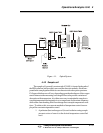
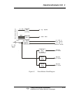
5.5.2 Power Supply Test Points
Measure +15 volt ±1 volt DC and -15 volt ±1 volt DC on the differential power
supply PC board in the control unit. Refer to the power supply schematic in the back
of the manual to identify the power supply test points.
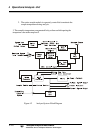
5.5.3 Setup of the Signal Processing Front-End
Amplifiers
Fill the sample cell with air or a stable fluid, such that the photo energy
that strikes the detector is constant. A stable fluid is distilled or tap water. This
step may be omitted when the system is stable in its present state.