


Part I: 2-9
Teledyne Analytical Instruments
Photometric Analyzer Part I: Control Unit
• Which alarms - if any - are tripped (AL-x ON)
Each status output is followed by a carriage return and line feed.
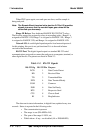
Three input functions using RS-232 have been implemented to date. They
are described in Table 2-4.
Table 2-4: Commands via RS-232 Input
Command Description
as<enter> Immediately starts an autospan.
az<enter> Immediately starts an autozero.
st<enter> Toggling input. Stops/Starts any status message output
from the RS-232, Until st<enter> is sent again.
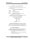
The RS-232 protocol allows some flexibility in its implementation. Table 2-
5 lists certain RS-232 values that are required by the 5000B.
Table 2-5: Required RS-232 Options
Parameter Setting
Baud 2400
Byte 8 bits
Parity none
Stop Bits 1
Message Interval 2 seconds
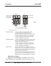
Remote Bench and Solenoid Valves: The 5000B is a single-chassis
instrument. However, the REMOTE BENCH and SOLENOID RETURN
connectors are provided on the interface PCB. The Remote Bench is wired
at the factory as well as any optional solenoid valves included in the system.
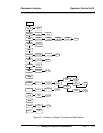
2.3 Testing the System
After The Control/Analysis Unit is both installed and interconnected, and
the system gas or liquid stream and electrical connections are complete, the
system is ready to test. Before plugging the unit into its power sources:
• Check the integrity and accuracy of the fluid connections. Make sure
there are no leaks.
• Check the integrity and accuracy of all electrical connections. Make
sure there are no exposed conductors