


4–3
Operations/Analysis Unit 4
Teledyne Analytical Instruments
A Business Unit of Teledyne Electronic Technologies
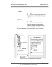
The control unit digital display must handle functions for both the analysis
section and the control module.
4.2 Start-p
Information contained in this paragraph is based on the premise that the
analyzer has been properly installed and that it is in operable condition. If
difficulties arise during start-up, it is probable that some form of damage has
incurred during shipment or some installation error has inadvertently been made.
Accessory test equipment is not necessary for start-up of the 5000B..
However, if the analyzer malfunctions at start-up, an oscilloscope and a
multimeter will be required for troubleshooting . TAI recommends that a dual
trace oscilloscope be used. A dual trace oscilloscope will permit the operator to
see two different waveforms simultaneously.
4.2.1 Preliminary Inspection
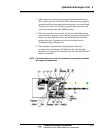
Before power is supplied to the analyzer, all modules should be opened
and inspected for damage or loose components. Plug-in circuit cards should
be firmly seated in their sockets. All barrier strip wiring connections must be
inspected, and user-installed wiring between units verified as being in agree-
ment with the system interconnection diagram.
Control Settings
Prior to turning on the power, the controls on and within the control
module should be positioned as follows:
Analyzers not equipped with Auto Zero
1. ON/OFF functionality hardwired at customers remote terminal
block or power switch.
2. SPAN control preset to the setting noted in Specific Application
Data in the Appendix.
Analyzers equipped with Auto Zero
1. ON/OFF functionality hardwired at customers remote terminal
block or power switch.
2. SAMPLE/ZERO switch on ZERO.
3. SPAN control preset to the setting noted in Specific Application
Data in the Appendix.