


Photometric Analyzer Operation /Control Unit 3
Part I 3-15
Teledyne Analytical Instruments
or
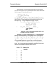
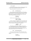
AUTOCAL FILSOL HOLD
CAL-HOLD-TIMER MORE
3. Using the Right or the Left arrow keys, select MORE and
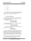
press Enter. The third System screen appears:
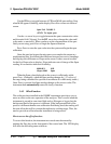
ALGORITHM APPLICATION
MODEL OUTPUT: 4 MA
or
ALGORITHM APPLICATION
MODEL OUTPUT: 20 MA
OUTPUT: 4 MA and OUTPUT: 20 MA can be toggled by moving on
that field and pressing the Up or Down key. 4 mA output should be calibrat-
ed first and 20 mA output afterwards.
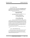
4. Select OUTPUT: 4 MA and press the Enter key
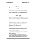
Use UP/DOWN arrow to
Adjust 4 ma: 250
The number on the second row is the setpoint of the 4 mA output. It is
analogous to a potentiometer wiper. The number can be set anywhere from
0 to 500. The default is 250, in the middle. At the default setting, the output
should be very close to 4 mA. If not, slowly adjust the number using the Up
or the Down keys until DMM reads 4.00 mA. Press the Enter key when
done.
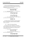
5. Now select OUTPUT: 20 MA and press the Enter key. A
screen similar to the one above will appear and the DMM should read close
to 20 mA. If not, slowly adjust the number using the Up or Down key until
DMM reads 20.0 mA. Press the Enter key when done.
The range of adjustment is approximately +/- 10% of scale (+/- 1.6 ma).
Since the 4 to 20 mA output is tied to the 0 to 1 volt output, this function can
be used to calibrate the 0 to 1 volt output, if the 4 to 20 mA output is not
used. By using a digital Volt meter on the 0-1 Volt output.
3.3.12 Model
This selection in the System menu flashes for a few seconds the model
number and the software version installed in this instrument.