


Photometric Analyzer Operation /Control Unit 3
Part I 3-11
Teledyne Analytical Instruments
The manual mode only requires entering the values for each correction
point into the microprocessor via the front panel buttons. Again, the number
of points required is determined by the user.
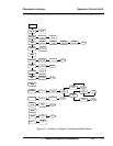
3.3.7 Digital Filter Setup
The 5000BF has the option of decreasing or increasing the amount
filtering on the signal. This feature enhances the basic filtering done by the
analog circuits by setting the amount of digital filtering effected by the
microprocessing. To access the digital filter setup, you must:
1. Press the System key to start the System function
DIG_FILT SELF-TEST
PWD LOGOUT MORE
2. DIG_FILT will flash, press the ENTER key,
Weight of digital
Filter: 9
3. The number on the second row will flash and can be set by
using the Up or Down arrow keys.
The settings go from zero, no digital filtering, to 10, maximum digital
filtering. The default setting is 8 and that should suffice for most applica-
tions. In some applications where speeding the response time with some
trade off in noise is of value, the operator could decrease the number of the
digital filter. In applications where the signal is noisy, the operator could
switch to a higher number; the response time is slowed down though.
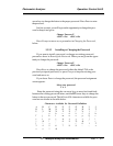
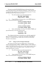
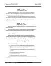
90% response time on the different settings to a step input is shown
below. This response time does not include the contributions of the bench
sampling system and the preamplifier near the detector.
Setting 90% Response time
(seconds)
0 4.5
1 4.5
2 5.0
3 5.0
4 5.5
5 7.0