


Photometric Analyzer Operation /Control Unit 3
Part I 3-9
Teledyne Analytical Instruments
3.3.4 System Self-Diagnostic Test
The Model 5000BF has a built-in self-diagnostic testing routine. Pre-
programmed signals are sent through the power supply, output board,
preamp board and sensor circuit. The return signal is analyzed, and at the
end of the test the status of each function is displayed on the screen, either as
OK or as a number between 1 and 1024. (See System Self Diagnostic Test in
chapter 4 for number code.) If any of the functions fails, the System Alarm is
tripped.
Note: The sensor will always show failed unless Zero fluid is present in
the sampling cell at the time of the SELF-TEST.
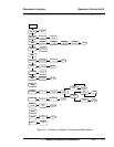
The self diagnostics are run automatically by the analyzer whenever the
instrument is turned on, but the test can also be run by the operator at will.
To initiate a self diagnostic test during operation:
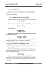
Press the System button to start the System function.
DIG_FILT SELF-TEST
PWD LOGOUT MORE
Use the < > arrow keys again to move the blinking to the SELF–TEST
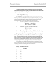
and press Enter. The screen will follow the running of the diagnostic.
RUNNING DIAGNOSTIC
Testing Preamp — Cell
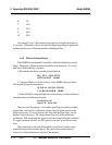
When the testing is complete, the results are displayed.
Power: OK Analog: OK
Cell: 2 Preamp: 3
The module is functioning properly if it is followed by OK. A number
indicates a problem in a specific area of the instrument. Refer to Chapter 5
Maintenance and Troubleshooting for number-code information. The results
screen alternates for a time with:
Press Any Key
To Continue...
Then the analyzer returns to the initial System screen.