


4–2
4 Operations/Analysis Unit
Teledyne Analytical Instruments
A Business Unit of Teledyne Electronic Technologies
4.1 Control Functions
4.1.1 Analysis Section, fully explosion proof, Z or X
purged Nema enclosure or Cenelec Purged (pending).
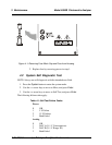
The control functions for the analysis section are located on the Front
of the Enclosure module:
1. POWER ON/OFF: This function is hard wired into the
enclosure for power to the control/analysis section.
2.a
X =
(C-A)(1000)
(B-A)
For example, if the range of analysis is 20-80%, and a desirable alarm
setpoint is 30%, then A = 20, B = 80, and C = 30
X =
(30-20)(1000)
= 167
(80-20)
2.b RANGE: Control unit allows changing the range by some
predetermined amount, such as 4X or 5X; i.e., triple range: low
range of 0-100 ppm, mid of 250ppm and a high range of 0-500
ppm.
3. Mode: Programmable functions for incorporating an automatic
zero, span or autoranging. Autocal also possible with fluids by
valving or by filter solenoid.. Consult control unit sections of the
manual.
4. Digital displayt: indicates the concentration of the component
of interest. Consult control unit section for setting up units as
ppm, mg/l, %, etc.
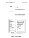
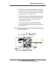
4.1.2 Explosion-Proof Version: Control Module
When the control module is integral with the analysis section (single explo-
sion-proof enclosure), it has all of the same control functions as the General
Purpose control module, however, the buttons are replaced by two switches.
These switches have different movements to achieve the same functionality as the
4 button model. (Consult factory or assure the manual has the correct version of
the front panel control switches and functions.