


3 Operation/Control Unit Model 5000B
3-18 Part I
Teledyne Analytical Instruments
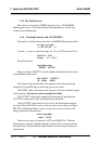
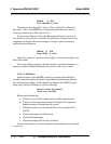
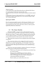
####.## % SO2
Zero adj:2048 C—Zero
The analyzer goes through C–Zero, F–Zero, and S–Zero. During C–
Zero and F–Zero, use the DÑ keys to adjust displayed Zero adj: value as
close as possible to zero. Then, press Enter.
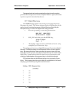
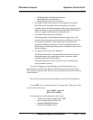
S–Zero starts. During S–Zero, the Microcontroller takes control as in
Auto Mode Zeroing, above. It calculates the differences between successive
samplings and displays the rate of change as Slope= a value in parts per
million per second (ppm/s).
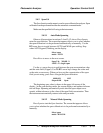
####.## % SO2
Slope=#.### S—Zero
Generally, you have a good zero when Slope is less than 0.05 ppm/s for
about 30 seconds.
Once zero settling completes, the information is stored in the analyzer’s
memory, and the instrument automatically returns to the Analyze mode.
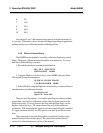
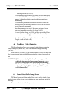
3.4.1.3 Cell Failure
Detector failure in the 5000BF is usually associated with inability to
zero the instrument with a reasonable voltage differential between the refer-
ence and measure voltages. If this should ever happen, the 5000BF system
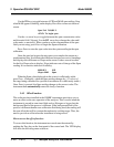
alarm trips, and the LCD displays a failure message.
Detector cannot be balanced
Check your zero fluid
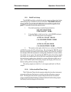
Before optical balancing:
a. Check your zero fluid to make sure it is within specifications.
b. Check for leaks downstream from the Sample Cell, where con-
tamination may be leaking into the system.
c. Check flowmeter to ensure that the flow is no more than 200
SCCM
d. Check temperature controller board.
e. Check fluid temperature.
f. Check the Sample Cell for dirty windows.
If none of the above, proceed to perform an optical balance as described
in section 5.