


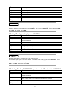
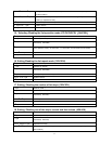

41
3
rd
byte
Command
(
24H/25H
)
4
th
byte The Lowest byte of max current value
5
th
byte The Lowest byte of max current value
6
th
byte The higher byte of max current value
7
th
byte The highest byte of max current value
From 8
th
to 25
th
byte System reserve
26
th
bye Sum code
NOTE
Represent an current value by 4 bytes of Hex .Lower bytes are in the front location, higher bytes are in the later
location.1 represent 0.1mA,If setting upper limit is
3.0000
A
,
the hex code is
0X00007530,
then the 4th byte is
0X30,
5th is
0X75,
6th is 0X00
,
7th is
0X00。
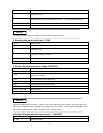
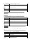
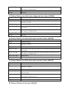
5. Setting / Reading max input power
(
((
(
26H/27H
)
))
)
1
st
byte Start bit ( AAH )
2
nd
byte Address (0—0XFE)
3
rd
byte
Command
(
26H/27H
)
4
th
byte The lowest byte of max power value.
5
th
byte The lower byte of max power value
6
th
byte The higher byte of max power value.
7
th
byte The highest byte of max power value.
From 8
th
to 25
th
byte System reserve
26
th
byte Sum code
NOTE
Represent power value by 4 bytes of Hex. Lower bytes are in the
Front location, higher bytes are in the later location. 1 represents 1mW. If setting upper value is
200.000W,
the hex
code is
0X00030d40,
then the 4th byte is
0X40,
5th is
0X0d,
6th is 0X03
,
7th is
0X00
.
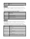
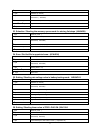
6. Selecting / Reading CC/CV/CW/CR operation mode of Electronic load.
(
((
(
28H/29H
)
))
)
1
st
byte Start bit ( AAH )
2
nd
byte Address (0—0XFE)
3
rd
byte
Command
(
28H/29H
)
4
th
byte
Mode
(
0 is CC mode, 1 is CV mode , 2 is CW mode , 3 is CR mode
)
From 5
th
to 25
th
byte System reserve
26
th
byte Sum code