


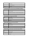
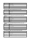

45
From 10
th
byte to 13
th
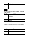
byte Setting value of resistance B (Lower bytes are in the front location, higher bytes are in
the later location)
From 14
th
byte to 15
th
byte Time value of timer B (Lower bytes are in the front location, higher bytes are in the later
location) (1 represent 0.1mS)
16
th
byte Transition operation mode (0 is CONTINUES,1 is PULSE,2 is TOGGLED)
17
th
byte to 25
th
byte System reserve
26
th
byte Sum code
15
.
..
.
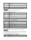
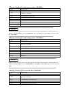
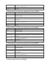
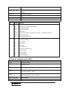
Selecting /Reading the list operation mode (CC/CV/CW/CR)
(
((
(
3AH/3BH
)
))
)
1
st
byte Start bit ( AAH )
2
nd
byte Address (0—0XFE)
3
rd
byte
Command
(
3AH/3BH
)
4
th
byte
LIST operation mode
(
0is CC mode
,
1 is CV mode ,2 is CW mode,3 is CR mode
)
From 5
th
to 25 byte System reserve
26
th
byte Sum code
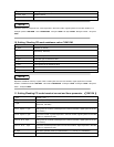
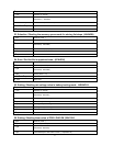
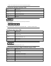
16. Setting /Reading the list repeat mode. (3CH/3DH)
1
st
byte Start bit ( AAH )
2
nd
byte Address (0—0XFE)
3
rd
byte
Command
(
3CH/3DH
)
4
th
byte LIST repeat operation mode(0 is ONCE, 1 is REPEAT)
From 5
th
to 25
th
byte System reserve
26
th
byte Sum code
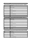
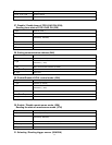
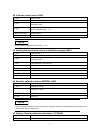
17. Setting / Reading the number of list steps. (3EH/3FH)
1
st
byte Start bit ( AAH )
2
nd
byte Address (0—0XFE)
3
rd
byte
Command
(
3EH/3FH
)
From 4
th
to 5
th
byte LIST steps
From 6
th
to 25
th
byte System reserve
26
th
byte Sum code
18. Setting / Reading one of the step’s current and time values. (40H/41H)
1
st
byte Start bit ( AAH )
2
nd
byte Address (0—0XFE)
3
rd
byte
Command
(
40H/41H
)
From 4
th
byte to 5
th
byte Appointed one step
From 6
th
to 9
th
byte Current value of current step (Lower bytes are in the front location, higher bytes are in the
later location)